Definition: Superposition Theorem states that voltage or current through an element of a linear, bilateral network having multiple sources is equivalent to the summation of generated voltage or current across that element, independently by each source present in the network. While at the time of considering a single source all other sources are replaced by their respective internal impedances.
In other words, we can say that when a bilateral network has multiple independent sources then the current or voltage through the circuit is determined by summing the individual responses achieved by considering each voltage or current source separately.
Basically, when we apply superposition theorem, the voltage and current sources are considered to be ideal.
Thus at the time of evaluating the voltage or current through the circuit element, the voltage source to be replaced is short-circuited and the current source is open circuited.
Now, let us proceed further to know what are the steps that one should follow in order to apply superposition theorem?
Steps to apply Superposition Theorem
- The first step is the selection of one of the sources among the multiple sources present in the bilateral network. Among the various sources in the circuit, any one of the sources can be considered first.
However, except the selected source, necessarily all the other sources must be replaced by their respective internal impedance.
- Now, the next step is applying a network simplification approach and evaluating the current flowing through or voltage drop across a particular element in the network.
Further, the same approach of considering a single source and determining the voltage or current through the element is done for all the other sources separately.
- Once, the respective response is obtained for each individual source, perform the summation of all the responses in order to get the overall voltage drop or current through that element in the circuit.
Consider the figure below, that shows the illustration of superposition theorem
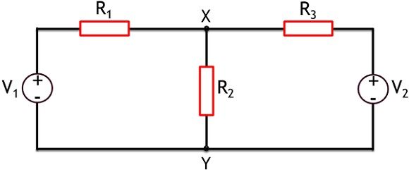
Here, as we can see that the network has 2 voltage sources V1 and V2 along with 3 resistances R1, R2 and R3.
Consider here that through superposition theorem we have to determine the current through branch XY.
So, applying superposition theorem, first the voltage source V1 is activated and V2 is changed by its internal impedance.
The figure below shows the representation of activation of V1,
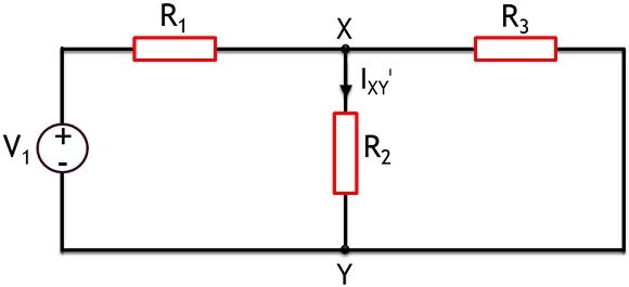
As we don’t know the internal impedance of V2 thus it gets replaced by a short circuit. This is clearly shown in the figure above,
So, by using network reduction technique the current through branch XY i.e., IXYᶦ can be calculated for the independent source V1.
In a similar way, for the next case, the source V1 is to be replaced by its internal impedance or short circuit. While V2 is active source for the next condition.
This is shown in the figure below:
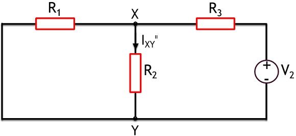
Now, again considering both the two meshes of the above network and applying a network reduction method, the current through branch XY can be obtained given by IXYᶦᶦ.
We know according to superposition theorem, the overall current flowing through branch XY is equal to the summation of current through that particular branch, by the action of both the individual sources.
Thus we can say,
IXY = IXYᶦ + IXYᶦᶦ
So, once the current through a particular branch is obtained by considering individual sources. Then the overall current can be determined.
Till now we have discussed the basis to determine the response of any network using superposition theorem. So, now let us consider an example to have a better understanding of the same.
Example
Let us consider an example to determine the current through branch AB by superposition theorem.
Have a look at the circuit shown below:
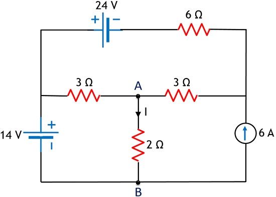
As we can see here that the circuit has 2 voltage sources and a current source. So in order to apply superposition theorem, firstly we will consider 14 V source and short-circuiting the 24 V source and open circuiting 3A source.
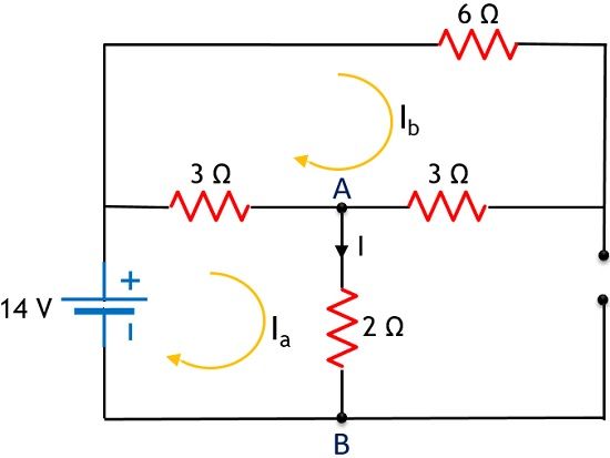
So, on applying KVL,
In mesh 1,
14 – 5Ia + 3Ib = 0
– 5Ia + 3Ib = – 14 ———— eqn 1
And in mesh 2,
0 + 3Ia – 12Ib = 0
3Ia – 12Ib = 0 ———- eqn 2
On solving the above two equations, we will get
Ia = 3.2 A
Ib = 0.8 A
However, the branch current, Iᶦ is equal to Ia in this case, thus,
I1ᶦ (for 12 V) = 3.2 Amp
Now, let us consider 24 V source and short-circuiting 14 V while open circuiting 6 A source.
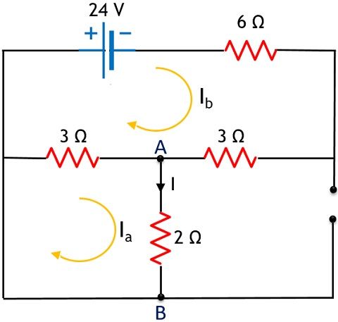
On applying KVL,
In mesh 1,
0 – 5Ia + 3Ib = 0
– 5Ia + 3Ib = 0 ———— eqn 3
And in mesh 2,
– 24 + 3 Ia – 12 Ib = 0
3 Ia – 12 Ib = 24 ———— eqn 4
On solving the above two equations, we will get
Ia = – 1.4 A
Ib = – 2.3 A
In this case, also the branch current is equivalent to the current flowing through mesh 1 i.e., Ia
So, I2ᶦ (for 24 V) = – 1.4 A
Moving further, let us now consider 3 A source, so 12 V and 24 V source will get short-circuited.
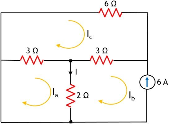
It is clear from the above figure that in this case, current Ib will be equal to – 6 A, so
So, current Ib for mesh 2 is – 6 A
On applying KVL,
In mesh 1, we will get
-5Ia + 2Ib + 3 Ic = 0
On substituting the value of Ib in the above equation,
-5Ia + 3 Ic = 12 ———— eqn 5
And applying KVL in mesh 3,
3 Ia + 3 Ib – 12 Ic = 0
Again substituting the value of Ib we will get,
3 Ia – 12 Ic = 18 ———— eqn 6
On solving the above 2 equations
Ia = – 3.8 A
Ib = – 6 A
Ic = – 2.4 A
Now, the branch current, in this case, will be
I3ᶦ (for 6 A) = Ia – Ib
I3ᶦ = – 3.8 + 6 A
I3ᶦ= 2.2 A
Hence the total current flowing through the circuit by all the 3 sources
Itotal = I1ᶦ + I2ᶦ + I3ᶦ
Itotal = 3.2 – 1.4 + 2.2
Itotal = 4 Amp
Limitations of Superposition Theorem
- The theorem is only applicable to non-linear circuit elements.
- It shows the invalid relationship in case of the power calculation.
- The operation of superposition theorem requires 2 or more independent sources.
So, this is all about superposition theorem and its explanation with example.