The acronym DECT stands for Digital Enhanced Cordless Telecommunications. It is a technology that offers wireless communication services for the transmission of voice, data, fax, multimedia, etc. This mechanism has brought cordless telephone systems into existence.
DECT is regarded as Digital Wireless Technology that was invented in Europe but has gained worldwide importance.
Content: DECT
Introduction
Digital Enhanced Cordless Telephone / Telecommunication is a digital cellular network that came into existence in the year 1992. Formerly the full form for DECT was Digital European Cellular Telecommunication however was renamed as ‘Digital Enhanced Cordless Telecommunication’. It was a replacement for older analog cordless phone systems.
Before 1994, this technology permitted communication between devices from the same manufacturer. However, in 1994, Generic Access Profile (GAP) came into existence and the concept enabled communication between devices that are not specifically designed by the same manufacturer.
Initially, DECT was invented with the aim to offer cordless telephone services to a smaller region such as an office building. However, with technological advancements the region of providing services has broadened up to campus-wide, this has increased its use in multiple fields. DECT includes additional multiplexing techniques that allow around 10000 users to get served within a region of approximately 1 km2.
The operating frequency range offered by DECT is around 1880 – 1990 MHz. Under this frequency range, 120 full-duplex channels can be served.
System Architecture
There are several uses of DECT systems and depending upon the usage there can be multiple physical techniques for the implementation of the system. But one thing which is to be kept in mind is that there is a single logical reference model of the system architecture which is the basis of all the implementations.
The figure given below shows the reference model of DECT system architecture:
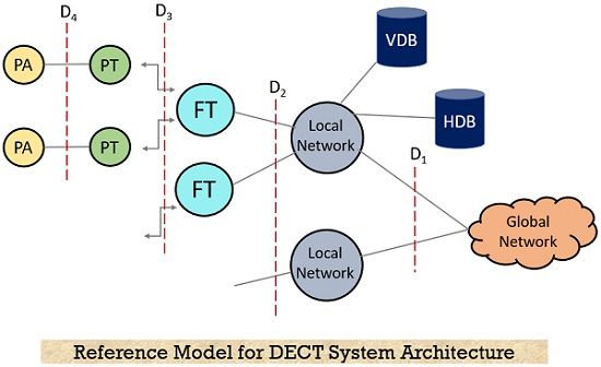
There is a local communication structure that is connected to the outside world through a global network and the services are offered via interface D1. Public Switched Telephone Network (PSTN), Public Land Mobile Network (PLMN), Integrated Services Digital Network (ISDN), etc. are the global networks. These networks allow the data transmission along with that the transfer of addresses and data routing between local networks also takes place.
A local network of DECT can provide local telecommunication services such as simple switching to any call forwarding, any type of address translation, etc. Some of its major examples are private branch exchanges i.e., the ones belonging to the family of LANs. The overall implementation of the system is simple and therefore, the overall functions that the network possesses are to be integrated within the local or global network, containing databases such as home database (HDB) and visitor database (VDB). The database operations here are similar to that of GSM systems.
In this case whenever there is a call in the local network then it gets automatically forwarded to the desired DECT user in the network and the necessary changes that occurred in the location are notified to the HDB by the VDB.
It is clearly shown in the above figure that there is a Fixed Radio Terminal (FT) and Portable Radio Terminal (PT) which are responsible for multiplexing of the signals to take place whenever necessary. The fixed radio terminal is placed at the fixed network side while the portable radio terminal exists at the mobile network side of the network. Along with these here we have multiple portable applications abbreviated as PA that a device can implement.
Protocol Architecture
The protocol architecture of the DECT system is based on the OSI reference model. Here we have shown the layers in the architectural representation containing physical layer, medium access control, and data link control that works for both Control Plane (C-Plane) as well as the User Pane (U-Plane).
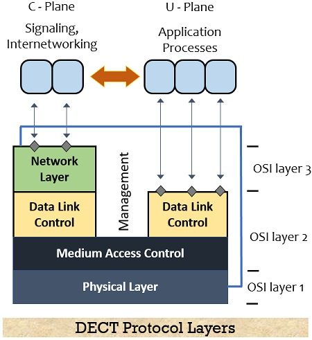
The C-plane contains the additional network layer used for forwarding the user data from one of the layers to the User-Plane. The lower layers of the DECT system belong to the management plane.
Let us now understand the operation of each layer briefly.
1. Physical Layer: The physical layer of the network is responsible for functions like detection of the incoming signal, performing modulation and demodulation, maintaining synchronization between sender and receiver along with collecting the status information for the management plane. The physical channel structure is obtained by this layer with guaranteed throughput. When data is required to get transferred which is notified by the MAC layer then the physical layer allocates the channel for the transmission of data.
In DECT, the standard TDMA frame structure used is shown here along with some data packets. The fundamental connection orientation over here is that there are 12 slots for uplink and downlink and the frame duration is 10 ms. While if we talk about an advanced connections scheme then in that case various allocation schemes can be implemented.
2. Medium Access Control (MAC) Layer: This layer is responsible for the activation and deactivation of physical channels in order to establish or release channels for higher layers. In the MAC layer, multiplexing of multiple logical channels onto physical channels is performed. While the logical channels that are present here are responsible for the transmission of user data, broadcasting or sending messages, paging, the network controlling, etc. Other than these some additional services provided by this layer are error controlling and correction along with division or reassembling of the packets.
3. Data Link Control Layer: It is abbreviated as DLC and is mainly responsible for forming connections between the mobile terminal and the base station. In this layer the Control Panel has assigned two services namely, one is paging which is assigned for connectionless broadcasting while the other is the point-to-point approach. Not only this, some other services include forward error correction, rate adaptation, and other services for enhancing the future system requirements.
Suppose if ISDN data is to be transferred at 64 kbit/s then the data transferred from DECT will also be 64 kbit/s. But in case, there is an error in the transmitted sequence then the rate of transfer is increased to 72 kbit/s and forward error correction is implemented. Also, ARQ is performed where a buffer of up to eight blocks is maintained. Due to this buffer delay of around 80 ms is also introduced in the transmitted sequence.
4. Network Layer: This layer works only for the control panel of the DECT structure and works in a similar manner as in ISDN and GSM. Mainly the services related to requesting, reserving checking, releasing, or controlling resources at fixed and mobile stations are offered by this layer. The necessary management relative to identity, authentication, or location is done by the Mobility Management (MM) present within the network layer. While there is Call Control (CC) which is responsible for handling the setting up, releasing, or managing the connection.
The DECT system is connected with the outside world through this layer as it enables connection-oriented message service and connectionless message service so that data transfer can take place between the networking unit.
Working of DECT
We have already discussed that two major components of any DECT system are the base station (the fixed part) and the mobile station (the portable part). Within a network, there can be multiple base stations and this generally suits in conditions where large telephonic coverage is needed. Here the mobile station is a cordless unit that forms a connection with the base station while it is also possible that the mobile station can be a handset or any smart device that supports communication.
Now, the question arises – how does a DECT operate?
The operation takes place in a way that the ‘beacon signal’ is sent by the base station. One must note here that beacon signals are the signals such as radio, ultrasonic, optical, laser, etc. that are generally regarded as satellite signals. These signals when sent through the base station are responsible for tracking the ground station or any respective radio operator.
So, here when the beacon signal which is sent by the base station is received by the mobile station in the network then the desired information is decoded so that a proper connection between the two stations can be made. Once the two stations get synchronized then a wireless connection will get made and a phone call can be easily established between them. When a phone call is going on within the network then no other beacon signal transmission will be handled in the meanwhile for the handset.
When the mobile station sends data to the base station then the delay introduced is around 10 ms. This delay is comparatively smaller than the delay which gets introduced when the signal is transmitted via Bluetooth or Wi-fi.
Advantages
- It offers a secure way of communication.
- The system is less prone to disturbances therefore chances of sound issues during calls are less.
- The handover process is easy.
- The offered frequency range of operation is quite high.
- Multiple mobile stations can be connected within a network.
- The DECT approach is regarded as energy efficient.
Applications of DECT
The DECT technique finds its major usage in Public Switched Telephone Network (PSTN), Wireless Private Branch Exchange (PABX), Global System for Mobile (GSM) access, Cordless Telephony, LAN connections, residential usage, etc.