Data Transfer Schemes are defined as the ways of transferring data or information between the processor and the peripheral devices/memory. Parallel Data Transfer Schemes allow various data bits to get simultaneously sent over parallel data lines.
The data transfer schemes facilitate smooth data communication within the system. Basically, anything that the processor does requires some sort of data over which the operation is to be performed. So, data transfer schemes are related to the methods through which data can be transferred between the units for the system’s operation.
There are various data transfer schemes and these show dependencies on parameters like type of I/O devices, type of processing along with the applications.
Content: Parallel Data Transfer Schemes
Need for Data Transfer
In order to execute any program, transferring the information plays a crucial role. Typically, in microcomputers, the transfer of data occurs between any two devices among the processor, IO devices, and memory. Generally, the data is transferred between either processor and IO device, processor and memory, or memory and IO device.
However, the timing parameters must be properly managed so that the transfer of data can take place in an efficient manner. The timing issues occur as the processor and IO device exhibit differences in operating time. In the case of magnetic memories, timing issues occur at the time of data transfer between processor and memory. While the semiconductor memories offer compatible timing with the processor so that data transfer can take place properly.
Classification of Data Transfer Schemes
The pictorial representation shown below gives the classification of data transfer schemes
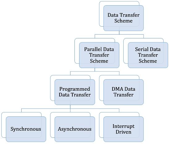
Mainly the parallel data transfer schemes are classified into two categories:
- Programmed data transfer
- Direct memory access (DMA) data transfer
Further, the programmed data transfer is sub-classified as:
- Synchronous
- Asynchronous
- Interrupt Driven
While the interrupt-driven data transfer can be either polled interrupts or vectored interrupts.
On the other side, the DMA data transfer is sub-classified as:
- Cycle Stealing DMA
- Block Transfer Mode DMA
- Demand Transfer Mode DMA
This content is centred around the parallel data transfer scheme.
Programmed Data Transfer
In this mode of transfer, the current user program which is under execution controls the data transfer. This scheme is mainly used where a small amount of data is needed to be transferred, meaning either one byte or one word of data is transferred at a given time.
The devices that use a programmed data transfer approach are ADC, DAC, Hex-keyboard, etc.
According to the type of device, the data transfer is categorized as synchronous and asynchronous.
1. Synchronous data transfer scheme: It is regarded as the simplest data transfer scheme in which the processor and the I/O device operate at matched speed with each other. More simply, here, in this case, the processor is not required to check the readiness of the I/O device as the two possessed matched timing parameters. So, in this scheme, whenever there is a need for data transfer exists, then the processor sends the read/write instruction to the device through a user program. The data transfer will get completed by the end of the execution of the instruction.
The figure shown below represents the synchronous data transfer scheme:
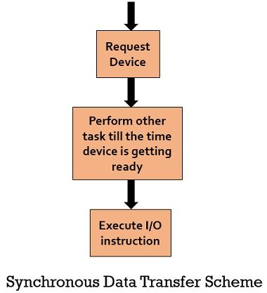
The sequence of the operation occurs as shown in the flow chart given above. Here, first, a request has been made for the device that data transfer is required. Till the time, the device is getting ready, other tasks can be performed in the meanwhile. Once the device gets ready for the data transfer then the input-output instruction is executed. This means here a small tolerated delay is involved at the time when the device is getting ready.
One of the examples of synchronous data transfer is mode-0 input/output in 8255.
2. Asynchronous Data Transfer: This data transfer scheme is implemented when there is a difference in the operating speed of the processor and IO device. More simply, if the speed of the IO device is slower than that of the processor then asynchronous data transfer takes place.
The figure given below represents the flow chart for the asynchronous data transfer scheme:
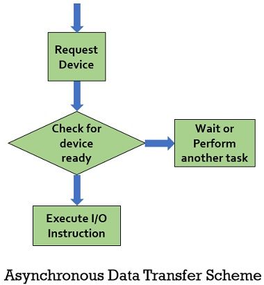
Initially, the request has been made by the processor to the IO device for read/write operation and after sending the request the processor keeps on checking whether the device is ready to transfer or not. After getting the ready signal the processor executes the data transfer instruction so as to complete the operation. Here in this scheme, the device must send the ready signal to the processor while it is waiting for the data transfer.
One of the examples of this scheme is mode-1 and mode-2 handshake data transfer of 8255 without interrupt.
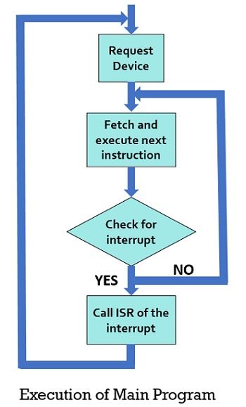
3. Interrupt-Driven Data Transfer Scheme: This is regarded as an efficient scheme that offers better utilization of processor time. We have recently discussed an asynchronous data transfer scheme, where the processor keeps checking for a ready signal from the IO device after making a request for data transfer. Due to this, the processor suffers from timing issues. This issue can be dealt with very well by an interrupt-driven IO scheme. Mainly after sending the request for data transfer, the processor inspite of waiting for a response from the IO device, the processor can begin to perform other instructions in the program. However, the processor will check for any generated interrupt regarding the device is ready after the completion of each instruction. In case no interrupt is generated, the processor will continue to perform the current execution.
By the use of interrupt, the processor without wasting time can perform other prioritized jobs. The processor is interrupted when there is any data transfer, execution of control sequence, or checking the status of any process.
The figure below represents the flow chart for interrupt-driven data transfer scheme:
Below we have shown the ISR execution sequence:
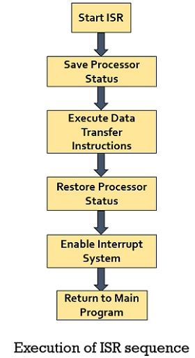
When the IO device is ready to transfer data then it will initiate an interrupt and once the processor gets the interrupt signal then it will complete the execution of its current instruction, save its status in the stack, and then ISR is called. Once ISR is called then the interrupt requesting device is serviced. After the data transfer has been completed the status of the processor is retrieved from the stack and execution of the main program begins.
DMA Data Transfer
It is the second type of parallel data transfer scheme where the processor remains in the HOLD state when data transfer is taking place between the IO device and memory. During the HOLD state, the processor will not perform any other task. It is generally used for transferring large blocks of data.