Definition: Transmission lines are the conductors that serve as a path for transmitting (sending) electrical waves (energy) through them. These basically forms a connection between transmitter and receiver in order to permit signal transmission.
Transmission lines in microwave engineering are known as distributed parameter networks. As their voltage and current shows variation over its entire length. It enables the transfer of electrical signals by a pair of conducting wires that are separated from each other by a dielectric medium which is usually air.
Content: Transmission Lines
Introduction
The figure below represents the equivalent circuit diagram of a transmission line:
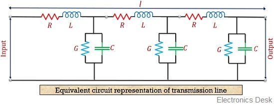
Here, the two conducting wires have a certain length and the parameters of the transmission line is distributed over all its length. These parameters are R, L, C and G which we will discuss in detail in the upcoming section. The two conducting wires due to separation holds some capacitance. But this dielectric medium does not provide complete insulation hence some leakage current flows through it.
Telephone lines and electricity supply lines are some examples of transmission lines.
Types of Transmission Line
Transmission lines are majorly classified into three categories:
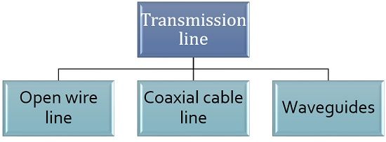
Open-wire transmission line: These are the conductors having 2 lines (wires), that are separated by dielectric medium whose, one end connected to the source and other to the destination. These are low cost and simplest form of transmission line. But, their installation cost is somewhat higher as well as its maintenance sometimes becomes difficult due to the change in atmospheric conditions.
The figure below represents the open-wire transmission line: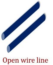
Coaxial cable lines: These lines are formed when a conducting wire is coaxially inserted inside another hollow conductor. These are termed as coaxial as the 2 conductors share the same axis. These are widely used in applications where high voltage levels are needed.
The figure shown below represents the coaxial cable transmission line: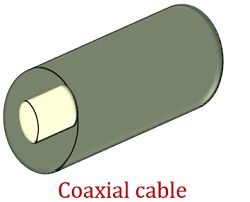
Waveguides: This category of the transmission line is used for signal transmission at microwave frequencies. These are basically hollow conducting tubes as they somewhat resemble like coaxial cable line but do not have centre conductor as present in coaxial cables.
The figure below represents the transmission line in the form of waveguide: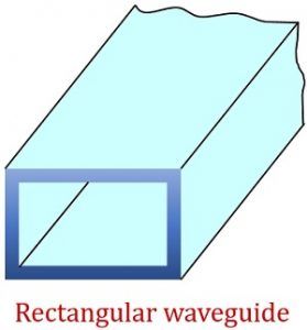
Parameters of the transmission line
During signal transmission through a conductor, it is necessary to have an idea about the parameters associated with it. So, basically, 4 parameters exist related to the transmission line.
- Resistance: This parameter of any transmission line relies on the cross-sectional area of the conducting material. As we have already discussed that these are distributed parameter networks that means its parameters are distributed uniformly along the entire length. It is represented by R and its unit is ohms per unit length of the conductor.
It is given by: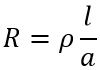
: ρ denotes the conductivity of the conducting material
l denotes the length of the transmission line and
a denotes the cross-sectional area of the line
It is noteworthy here that the resistance shows the variation with temperature and signal frequency applied to it.
- Capacitance: As we have already discussed that a transmission line is composed of 2 parallel conducting wire separated by dielectric material. So it behaves as a parallel plate capacitor. Thus it has some capacitance which is also distributed uniformly over its length. It is measured in farads per unit length of the conductor.
- Inductance: When current flows through a conductor then it generates a magnetic field perpendicular to the direction of the electric field. As the magnetic field varies, electromagnetic flux gets generated in the line. So, this emf now flows in opposite direction with the current flowing through the device which is known as inductance. Its value depends on the current flowing through the conductor. Inductance is represented by L and its unit is Henry per unit length of the conductor.
- Conductance: The two parallel conductors are separated by a dielectric medium but it is not a perfect insulator. Due to which some current also flows through the dielectric. This current is called leakage current and it is responsible for leakage conductance through the transmission line. It is basically present between the conducting wires and is represented by G. Its unit is mho per unit length of the conductor. So, the four parameters of a transmission line are represented as R, L, C, and G.
Properties of Transmission Line
A transmission line that allows the propagation of electrical waves is assumed to be uniform as well as symmetrical in nature so as to have a convenient transmission. So, basically, there exist 2 electrical properties of any symmetrical network.
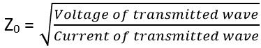
- Characteristic Impedance (Z0):
Suppose an electrical wave is traveling from one end to another through a uniform as well as a lossless transmission line. Then the ratio of voltage corresponding to the transmission line and the equivalent current that is flowing through it is known as characteristic impedance. It is to be noted here that no reflection of the transmitted wave will take place. It is given by:
In terms of parameters characteristic impedance is represented as:
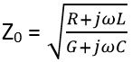
When we consider a completely lossless transmission line, then it is given as:

The symmetrical network is said to be accurately terminated when the characteristic impedance at it’s both ends is equalized.
- Propagation Constant (ϒ):
The propagation constant of a transmission line is defined as the ratio of current achieved at the output to the current applied at the input of the system. It is given as
: ϒ denotes a complex quantity represented by α + jβ
Here α is the attenuation constant and β is the phase constant.
Applications of Transmission lines
For the transmission of a signal having a high-frequency range over short as well as long distance, transmission lines are used. At the same time, this reduces the loss of power during transmission. These are also used in stub filters, in stub matching technique and in voltage transformer.