Definition: A magnetron is a device that generates high power electromagnetic wave. It is basically considered as a self-excited microwave oscillator. And is also known as a crossed-field device.
The reason behind calling it so is that the electric and magnetic field produced inside the tube are mutually perpendicular to each other thus the two crosses each other.
Content: Magnetron
- Operating Principle
- Construction
- Working
- Frequency Pushing and Pulling
- Advantages
- Disadvantages
- Applications
Operating Principle
A magnetron is basically a vacuum tube of high power having multiple cavities. It is also known as cavity magnetron because of the presence of anode in the resonant cavity of the tube.
The operating principle of a magnetron is such that when electrons interact with electric and magnetic field in the cavity then high power oscillations get generated.
Magnetrons are majorly used in radar as being the only high power source of RF signal as a power oscillator despite a power amplifier. It was invented in the year 1921 by Albert Hull. However, an improved high power cavity magnetron was invented in 1940 by John Randall and Harry Boot.
Here in this article, we will discuss how a cavity magnetron works. But before that, we must know how a magnetron is constructed.
Construction of Magnetrons
The figure here shows a magnetron with 8 cavities: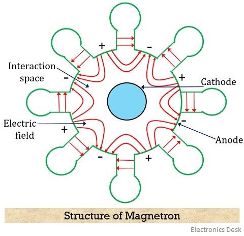
A cylindrical magnetron has a cylindrical cathode of a certain length and radius present at the centre around which a cylindrical anode is present. The cavities are present at the circumference of the anode at equal spacing.
Also, the area existing between anode and cathode of the tube is known as interaction space/region.
It is to be noted here that there exists a phase difference of 180⁰ between adjacent cavities. Therefore, cavities will transfer their excitation from one cavity to another with a phase shift of 180⁰.
Thus we can say that if one plate is positive then automatically its adjacent plate will be negative. And this is clearly shown in the figure given above.
More specifically we can say that edges and cavities show180⁰ phase apart relationship.
As we have already discussed that here the electric and magnetic field are perpendicular to each other. And the magnetic field is generated by using a permanent magnet.
Working of Magnetron
The excitation to the cathode of the magnetron is provided by a dc supply which causes the emergence of electrons from it.
Here in this section, we will discuss the working of magnetron under two categories. First without applying the RF input to the anode and the second one with the application of RF input.
1. When RF input is not present
Case I: When the magnetic field is 0 or absent
When the magnetic field is absent then the electron emerging from the cathode radially moves towards the anode. This is shown in the figure below:
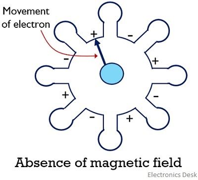
This is so because the moving electron does not experience the effect of the magnetic field and moves in a straight path.
Case II: When a small magnetic field is present
In case a small magnetic field exists inside the magnetron then the electron emerging from the cathode will slightly deviate from its straight path. And this will cause a curvy motion of the electron from cathode to anode as shown in the figure: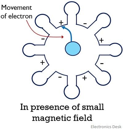 This motion of the electron is the result of the action of electric as well as magnetic force over it.
Case III: In case when the magnetic field is further increased then electrons emerging from the cathode gets highly deflected by the magnetic field. And graze along the surface of the cathode, as shown below: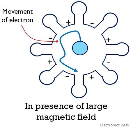 This causes the anode current to be 0. The value of the magnetic field that causes the anode current to become 0 is known as the critical magnetic field.
If the magnetic field is increased beyond the critical magnetic field. Then the electron will bounce back to the cathode itself without reaching the anode.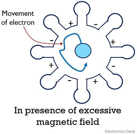
The reaching of the emitted electrons from the cathode back to it is known as back heating. So to avoid this the electric supply provided to the cathode must be cut-off after oscillations have been set up in the tube.
2. When the RF field is present
Case I: In case an active RF input is provided to the anode of the magnetron then oscillations are set up in the interaction space of the magnetron. So, when an electron is emitted from the cathode to anode then it transfers its energy in order to oscillate.
Such electrons are called favoured electrons. In this condition, the electrons will have a low velocity and thus will take a considerably high amount of time to reach from cathode to anode.
This is given in the figure below: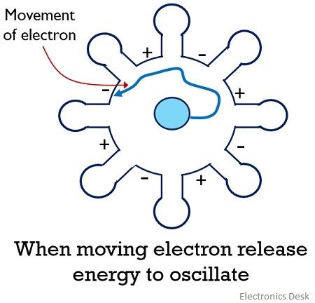
Case II: Another condition arises in the presence of RF input. In this case, the emitted electron from the cathode while travelling takes energy from the oscillations thereby resultantly increasing its velocity.
So despite reaching the anode, the electrons will bounce back to the cathode and these electrons are known as unfavoured electrons.
The propagation of unfavoured electrons is shown below: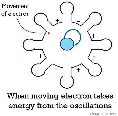
Case III: When the RF input is further increased then the electron emitted while travelling increases its velocity in order to catch up the electron emitted earlier with comparatively lower velocity.
So, all those electrons that do not take energy from the oscillations for their movement are known as favoured electrons. And these favoured electrons form electron bunch or electron cloud and reaches anode from the cathode.
The formation of electron bunch inside the tube is known as phase focusing effect.
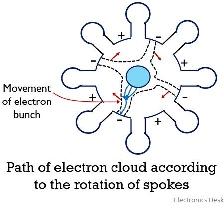
Due to this, the orbit of the electron gets confined into spokes. These spokes rotate according to some fractional value of electron emitted by the cathode until it reaches anode while delivering their energy to oscillations.
However, the electrons released from the region of cathode between spokes, will take the energy of the field and get back to the cathode very quickly. But this energy is very small in comparison to the energy delivered to the oscillations. This is shown in the figure below:
The movement of these favoured electrons inside the tube enhances the field existing between the gaps in the cavity. This leads to sustained oscillations inside the magnetron thereby providing high power at the output.
Frequency Pushing and Pulling
The variation in the oscillating frequency of the magnetron give rise to the term frequency pushing and pulling.
When the voltage applied at the anode of the magnetron is varied then this causes the variation in the velocity of the electrons moving from cathode to anode. This resultantly changes the frequency of oscillations.
Therefore, we can say when the resonant frequency of the magnetron shows variation due to the change in the anode voltage then it is known as frequency pushing.
The change in resonant frequency is sometimes a result of the change in the load impedance of the magnetron. The load impedance varies when the change is purely resistive or reactive. This frequency variation is known as frequency pulling. A steady power supply can provide a reduction in this frequency variation.
Advantages
- Magnetrons are a highly efficient device used for generation of the high power microwave signal.
- The use of magnetrons in radar can produce radar system of better quality for tracking purpose.
- It is usually small in size thus less bulky.
Disadvantages
- It is quite expensive.
- Despite producing a wide range of frequency, there exists a drawback in controllability of the generated frequency.
- It offers average power of around 1 to 2 kilowatts.
- Magnetrons are quite noisy.
Applications of Magnetron
- A major application of magnetron is present in a pulsed radar system in order to produce a high-power microwave signal.
- Magnetrons are also used in heating appliances likes microwave ovens so as to produce fixed frequency oscillations.
- Tunable magnetrons find their applications in sweep oscillators.
It is noteworthy here that this mode of operation of the magnetron is also known as π mode. This is so because a proper phase shift of 180⁰ is maintained between two adjacent plates. Also, it is to be noted that oscillations are only built-up in π mode.
Very very helpful
This is soo easy to understand
Thank you
Very helpful thanks
Amazing