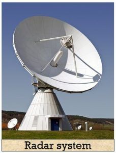
Definition: RADAR is an abbreviation for RAdio Detection And Ranging. A system used for detecting and locating the presence of objects like ships, vehicles, aircraft etc. by radiating electromagnetic signal in space is known as the Radar system.
Basically, radar is used to collect the information related to the object or target like its range and location by radiating electromagnetic energy and examining the echo received from the distant object.
Content: Radar System
History
Radar was invented for military purpose before world war II in order to secretly detect the presence of unknown objects. Initially, the transmitting tubes were not that much powerful thus worked at a very low frequency of about 60 MHz.
But further development in the field and use of magnetrons has extended the frequency range to a higher level.
According to the operation performed by the radar, it is very important to have a system that can accurately detect the presence of the target. So for this purpose, narrow beam antennas with short-wavelength are used that correspond to upper UHF and microwave frequencies.
Thus the US army developed microwave radar system and such a system can determine the position of the object to within 0.1° and 25 meters.
Principle
A radar system operates in a way that it radiates electromagnetic energy into space and detects various aspects related to objects by analysing the echo generated when the radiated energy gets re-radiated by the object.
The figure below shows the basic principle of radar: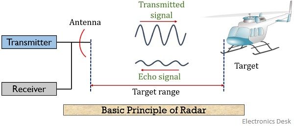
The electromagnetic signal is produced by the transmitter unit and is radiated in space by the radar antenna. While the receiver performs extraction of information from the signal received by the radar antenna.
We know whenever an electromagnetic wave is transmitted by the system then it reflects or re-radiates some of its parts on experiencing a variation in the conductivity of the medium. This variation in conductivity arises due to the presence of an object either stationary or moving. Thereby producing an echo.
The radar system receives the echo by the help of an antenna in order to analyse it and have the location of the object.
Now the question arises how the reception of an echo can determine the range and location of the target?
Range specifies the distance between the target and the radar system.
The range to an object is determined by the measurement of the time taken by the radiated signal to reach the object and come back to the radar. And the location of the stationary object in the space is determined from the angle pointed by the antenna when the echo received is of maximum amplitude.
For a moving object because of the Doppler effect, there exists a shift in the frequency of the re-radiated signal. And the frequency shift shows proportionality with the radial velocity of the object.
Basically, there exist two major radar systems:
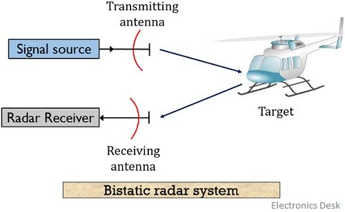
Monostatic Radar System: A monostatic radar system uses a single antenna for transmission as well as reception purpose.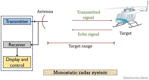 Bistatic Radar System: A bistatic radar system utilizes independent antennas for transmission and reception of the signal.
Block Diagram of Radar System
The figure below shows the block diagram representation of radar:
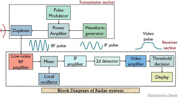
We know that a radar system has a transmitting and receiving section. And both the sections perform their respective operation.
Let us now discuss how radar operates:
Transmitter Section: The transmitter section is composed of the following units:
1. Waveform Generator: The waveform generator (usually a magnetron) generates a radar signal at low power which is to be transmitted into space.
2. Transmitter: The signal generated by the waveform generator is fed to the transmitter. The transmitter section can be a magnetron, travelling wave tube or a transistor amplifier.
In the case of pulse radar, magnetrons are widely used as transmitters but whenever there exists a need for high average power then amplifiers are used.
3. Pulse modulator: A pulse modulator is used to build synchronization between the waveform generator and transmitter.
The pulse modulator causes the turning on and off of the power amplifier according to the input pulses generated by the waveform generator.
4. Duplexer: A duplexer is basically used to form isolation between transmitter and receiver section. A duplexer allows the use of a single antenna for both transmission and reception purpose. However, both the sections operate at different power level, therefore, a duplexer is used to isolate the two section.
Thus the signal from the transmitter is provided to the antenna through the duplexer. As the duplexer short circuits the input of the receiver section.
Also, the re-radiated signal received by the common antenna is fed to the receiver section using duplexer.
Receiver Section: The following components are present inside the receiver section:
5. Low noise RF amplifier: The receiver must be superheterodyne. The unit acts as the input stage for the receiver section. The RF amplifier generates an RF pulse which is proportional to the echo of the transmitted signal.
6. Mixer and Local Oscillator: The RF pulse received from the low noise RF amplifier is converted into an IF pulse. Usually, the RF amplifier acts at the input stage of the receiver section but sometimes the mixer acts at the input stage by eliminating the RF amplifier.
But this leads to a less sensitive receiving section due to the high noise figure of the mixer.
7. IF amplifier: The IF pulse generated by the mixer circuit is amplified by the IF amplifier. It acts as a matched filter and increases the SNR of the received signal. Also, it enhances the echo detecting ability of the receiver section by reducing the effects of unwanted signals.
The receiver’s bandwidth is associated with the bandwidth of the IF stage.
8. 2nd Detector or Demodulator: This unit is nothing but a crystal diode that performs demodulation of the signal by separating the transmitted signal from the carrier.
9. Video Amplifier: This unit amplifies the received signal to a level that can be displayed on the screen.
10. Threshold decision: This unit makes the decision about the existence of the target in space. Basically, it has some threshold limit set which is compared with the magnitude of the received signal.
If the threshold value is surpassed by the output signal, then this shows that presence of the target. Otherwise, it is assumed that only the noise component is present in the space.
11. Display: The display unit shows the final output of the receiver section. PPI i.e., plan position indication is typically used as the radar display unit.
It presents the range and location of the object by mapping it in polar coordinates. PPI is implemented with CRT.
The output signal modulates the electron beam of the cathode ray tube in order to permit the electron beam to sweep from the centre in the outward direction of the tube. And this sweep shows rotation in synchronization with the pointing of the antenna.
Applications of Radar
Radar systems find its applications in a wide variety of fields like military, air traffic control, in weather forecasting, remote sensing, astronomy, mapping etc.
- Military: It is the major application of radar and is one of the most important parts of the air defence system. Radar is used for the purpose of navigation and surveillance in the military for secure operations.
- Air traffic controlling: Radar is used to control the air traffic in the air routes and airports. High-resolution radars are used for analysing the aircraft and ground vehicular traffic at the airports.
- Ship safety: Radars are used to provide safety measures to the ships in bad visibility conditions by giving alerts about the existence of other ships in the route.
- Remote sensing: Radar is a remote sensor by nature as they can sense the geophysical objects. And these are used forecasting of weather conditions along with agricultural conditions and environmental pollution.
This is all about the introduction, block diagram and operation of the radar system.