Image Orthicon is a photoemissive type of camera tube. Photoemission is the basis of its working. This camera tube was invented in the year 1945 by Radio Corporation of America.
Photocathode acts as a primary element in the operation of image orthicon. This is so because photocathode allows the emission of electrons from its surface when light from a scene is allowed to incident on it.
We know the basic operation of camera tubes includes the change of optical energy into electrical energy. And to achieve this, an image orthicon makes use of photoemissive material i.e., photocathode.
Content: Image Orthicon
Construction of Image Orthicon
The figure below represents the structure of image orthicon:
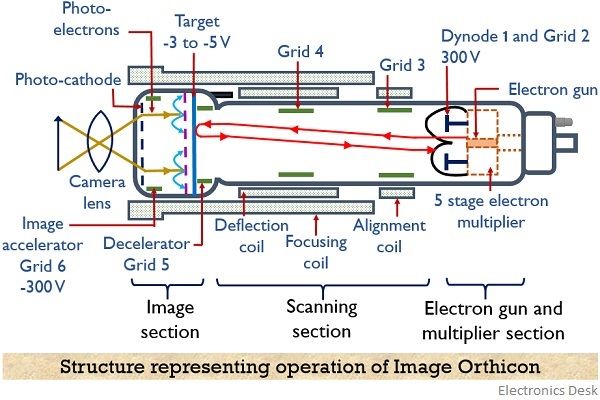
As it is clear from the above figure that the whole structure is divided into 3 sections which are as follows:
- Image section,
- Scanning section and
- Electron gun and multiplier section.
The image section consists of photocathode formed by coating the inner surface of a glass faceplate with silver-antimony-cesium. A lens system is used that focuses the image from a scene on the surface of the photocathode.
This incident light from the image allows the emission of electrons from the surface of the photocathode.
The surface of the photocathode is semi-transparent in nature. Thereby allowing penetration of incidenting light into the inner surface from where the electron emission is taking place.
Photocathode emits the charge stored in it by the action of light energy. Therefore, the structure is designed in a way that electrons emitted from the surface of the photocathode are accelerated towards the target plate.
The voltage provided to:
- photocathode is -400 V,
- target plate made of thin glass sheet is nearly 400 V more positive than the photocathode.
- image accelerator present in the image section (denoted as grid 6) is nearly around -300 V.
- a decelerator grid present in scanning section is 40 V and
- Grid 6 is at high positive potential wrt photocathode, allowing the attraction of the emitted electrons.
Also, a thin wire-mesh screen is placed which is composed of 300 meshes / cm2 at a distance of 50 to 75 microns from the target plate to avoid interference with electron image.
In the structure of image orthicon, the focusing coil allows focused striking of the electron beam at the target. The structure holds the electron gun and multiplier stage that provides the desired video signal.
Working Principle of Image Orthicon
The working of image orthicon is explained in detail under the three sections, so consider the above figure and proceed:
Image Section
When light from a scene falls on the surface of photocathode then electrons are emitted from its surface. Due to the semi-transparent nature of the cathode surface, the light penetrates in order to reach the inner surface of the material.
The number of emitted electrons will be directly proportional to the intensity of the optical image falling on the surface.
The emission of electrons from the surface of the cathode leads to the formation of an electron image on the target side of the photocathode.
- Being a conductor with high conversion efficiency, the photocathode cannot hold the charge in it. Therefore, the produced electron image moves towards the target plate present in the image section at some distance from the cathode.
As we have already discussed under construction that potential at the target plate is comparatively higher than the potential at the photocathode. Thus the resultant electric field provides proper acceleration, thereby allowing the movement of electrons towards the target plate.
But the electrons in motion possess the tendency of repelling each other while moving, and this resultantly distorts the information present in the form of charge image.
So to avoid this, an axial magnetic field is provided by the use of a focusing coil. The magnetic field focusses the emitted electrons on the surface of the target plate in the form of definite electron image of the actually provided optical image.
- On the target plate towards the side of cathode, cesium (caesium) is deposited that provides a high ratio of secondary emission.
The high-velocity electrons emitted from the surface of the photocathode when bombards the surface of the target then secondary electrons are emitted from the surface of the target.
The wire-mesh screen present in front of the target plate collects these secondary electrons. Due to the emission of secondary electrons, a positive charge distribution is created on the surface of the target plate.
This distribution of positive charge on the target surface is proportional to the intensity of incidenting optical image on the surface of the photocathode.
As we have already discussed that target is made of the thin glass sheet, this is basically done to prevent the spreading of stored charge over the surface of the target. As spreading of charge will hinder the resolution of the device.
- A noteworthy point over here is that in order to have a continuous distribution of positive charge on the target, the light from the scene must be continuously provided to the photocathode, to allow the cumulative process.
As the presence of cesium at the target surface provides high secondary emission ratio. Therefore, this leads to higher intensity of positive charge distribution at the target than charge produced (emitted) by the photocathode.
This increase in charge density at the target wrt charge at the photocathode is called image multiplication. This resultantly enhances the overall sensitivity of the image orthicon.
Due to the thin structure of the target plate, the stored positive stored charge appears on the other side of the target which is subjected to scanning. And the video signal is achieved from this particular side of the target plate.
To facilitate the neutralization of stored charge, a scanning electron beam is used. Let us now understand the further process.
Scanning Section
The electron gun emits an electron beam for scanning the charges at the target plate. Basically, the beam emitted by the cathode of the gun is focussed towards the target by the help of the magnetic field produced by an external focus coil and the potential at grid 4.
The potential at the target is nearly 0 V thus electrons in motion stop their movement at the target surface. To prevent the emission of secondary electrons at the surface of the target, certain deceleration is provided to the beam approaching the target by grid 5.
So, the electrons in the beam reaches the target with almost zero velocity and neutralizes the positive charge present on the plate. But only the number of electrons required to neutralize the positive charge is deposited on the plate while the rest returns towards the first electrode of the multiplier.
- This deposition of charge occurs in less than a frame time due to low resistivity towards both sides of the target.
But as continuous generation of positive charge is taking place at target due to continuous incidenting of the optical energy. Therefore, after each scanning beam, the target will again hold the positive charge.
- In the absence of any positive charge, deposition of charge at the target will not take place and the beam will return to the electron gun.
As a constant amount of electrons are emitted by the beam for each scanning. Thus after each scanning different amount of electrons will be deposited on the target surface and rest will move towards the gun.
And the deposition will depend on the positive generated charge according to the intensity of incident light (or the picture information) at the photocathode.
- This leads to the conclusion that the signal current will be high for dark regions of the image and low for bright regions. The reason behind this is that
- For dark regions, the absence of light will not cause electron emission from the surface of the photocathode. Thus no secondary emission will take place at the target and resultantly no electrons will be required to neutralize the positive charge at the target. So the scanning beam will return to the electron gun, giving rise to high current.
- As against for bright regions, the presence of light, give rise to electron emission and so to the positive charge at the target. Thus electrons from the scanning beam will be needed for charge neutralization. Hence there will be a reduction in amplitude of current from the return beam.
It is to be noted here that a low-velocity beam when approaches the target, tries to glide along its surface in tangential manner and this causes loss of resolution.
Thus, it is required that the scanning beam must strike the target at the right angle to achieve good resolution. And so to achieve this combined action of electrostatic and magnetic field must be utilized.
Hence the interaction of two fields causes cycloidal motion of the beam that leads to striking the target at right angle irrespective of the scanning point.
Electron multiplier section
The beam returning from the target plate reaches a disc which covers the gun electrode present close to the aperture from where the beam emerged.
The potential at the disc is nearly 300 V wrt the target and this disc acts as the initial stage of the multiplier.
The figure below shows the complete multiplier stage which is composed of 5 different stages having different potential:
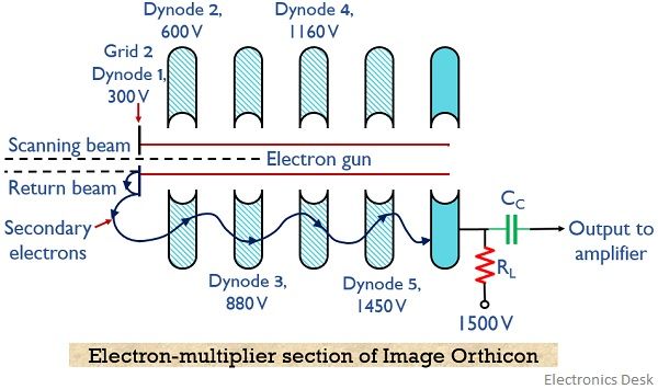
The return beam when strikes the disc then secondary emission of electrons takes place. So, these secondary electrons get attracted towards the dynodes present at successively greater potentials, as shown in the figure shown above.
- A gain of approximately 4 is provided by each stage of the multiplier. Thus the overall gain provided by the multiplier section will be (4)5 nearly 1000.
And therefore called signal multiplication, thereby providing high SNR. The anode connected with the highest supply of +1500 V with RL finally collects the secondary electrons.
The variation in the anode current is proportional to the variation existing in the return beam from the target and amplification by the multiplier.
Thus we can say that voltage across load resistor RL is the required video signal. And its amplitude is dependent on the brightness variation of the optical image.
Applications
Image orthicon camera tubes were initially used in studios for live shows and for remote pickups that require the accommodation of a wide range of lighting conditions.