Definition: A video switcher is a crossbar switch that allows selection of one or more desired sources or inputs from multiple sources so as to generate a complete program. It is also known as a vision mixer.
It is basically a switch matrix that selects either one or more input out of various inputs to the outgoing circuits.
Basic Concept
The multiple input sources are camera, telecine, VCR and test signals etc. Thus the program producer makes use of video switcher for either selecting the output of any camera or combining the outputs of multiple cameras.
Sometimes effects like fade, supers, dissolves, wipes may get introduced at the time of production of the program. Thus these effects are also controlled using a mixer.
Typically vision mixer is a 10 * 6 or 20 * 10 crossbar switch that selects 6 or 10 output lines from 10 or 20 inputs lines respectively.
When source sync matches with the station sync then it is called synchronous source. As against, when source sync shows independency with the station sync then it is said to be a non-synchronous source.
By the help of switching even a camera output that is restricted to a 2D image can be made to be displayed with a different angle. Along with this the image displaying on multiple screens at different locations can be displayed on a single screen.
The output of a video switcher can be a transmitter unit, a VTR or a string of monitors in case of a CCTV system.
TV programs can be edited by video switchers that holds the following operational characteristics:
- Selecting any input or switching from one input to another.
- Fading in and out.
- Providing caption in case of superposition of two inputs in the background.
- Providing a selection of wipe pattern in case of split-screen.
- Switching from one input to another ensuring overlapping.
It is to be noted here that some technical requirements must be fulfilled by the switcher at the time of mixing. These are as follows:
- During switching between synchronous sources, sync disturbances must not exist. Even in the case of non-synchronous sources, the maximal permissible sync disturbance is 1 ms.
- At the time of fading, excessive distortion must not be introduced by the circuit. Practically full fade allows 2%, mid-position permits 5 % and rest other positions allow around 15% of permissible distortion.
Block Diagram of Video Switcher
The figure below represents the block diagram of an electronic video switcher:
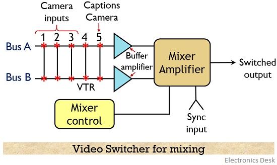
As we can see clearly that here we have two data bus i.e., A and B and so total there are 5 inputs and two buffer amplifiers whose output are fed to a mixer-amplifier. Therefore, 2 camera inputs are selected out of the overall 5 inputs that drive the 2 buffer amplifier.
The output signal of these buffer amplifiers are then fed to a mixer-amplifier.
Fade-out fade-in method is utilized by the mixer for transferring the video signals. It is to be noted here that the information from either bus A or bus B is positioned to have 100 % selection by the potentiometer present in the mixer-amplifier.
Suppose bus A and B are set at a level of 0 and 100 % respectively. Also, camera 3 is selected at bus A while camera 1 is selected at bus B. Thus, in this case, the output of camera 3 will not appear at the mixer whereas the output of camera 1 will be present at the same.
Also, the sync input is provided to the mixer-amplifier in order to have proper vertical switching.
Thus in this way switchers can be designed to have various switching matrices.
Types of Video Switcher
There exist broadcast switchers that utilizes vertical blanking interval controlled switching. Switching of signals during the vertical blanking period removes visible evidence of switching that is represented by interruption at the time of vertical scanning.
Video Switchers mainly are of 3 types:
1. Mechanical Pushbutton Switcher: In this type of switcher the video signals majorly exist on the actual switch contacts. Also, to avoid the occurrence of simultaneous punching, the blanks of the switches are interlocked.
These are widely used in the case where there exists a need for a portable unit like CCTV systems. This is so because this technique does not let frequent switching and even the disturbances generated can be tolerated.
2. Relay Switcher: It is known as an electromechanical switcher. This is so because the reed switch contacts are activated magnetically in this type of switcher. The operational time is around 1 ms thereby providing speedy operations.
Loss of sync at the time of switching is prevented by such a small difference in switching interval. It is also known as D-switching.
3. Electronic Switcher: In electronic switchers, solid-state devices are used that provides a vertical blanking interval of few microseconds. The information of the previous switching is stored in memory till the time next sync pulse arrives. It offers advantages like small size, low maintenance and high reliability thus find major applications in modern broadcasting switchers.
A special effects generator is a unit present with camera control units that provide special effects to the video signals like curtain moving effects, which are used as a transition for a change from one scene to another.
So, like this various other effects can be added between two separate programs.