Definition: An oscillator is basically a signal generator that produces a sinusoidal or non-sinusoidal signal of some particular frequency. Oscillators find their various applications as these are the fundamental component of any electrical and electronic circuits.
Continuous oscillations are the basis of working of an oscillator. Sometimes, an oscillator is said to be an amplifier with positive feedback. Or more specifically, a feedback amplifier with an open loop gain equal to or somewhat greater than 1.
At the time of defining, we say oscillators are generators. But more specifically, oscillators are energy converter that transforms dc energy into equivalent ac energy. The frequency ranges of the ac signal at the output of oscillator ranges from a few Hz to several GHz.
We are already aware of the fact that an amplifier needs ac input signal that is amplified and achieved at the output of the amplifier. However, oscillator simply requires dc voltage in order to produce ac signal of desired frequency.
The oscillator is mainly classified on the basis of the signal generated at its output:
- Sinusoidal or Harmonic Oscillator: Here the achieved signal at the output of oscillator shows continuous sinusoidal variation as a function of time.
- Non-sinusoidal or Relaxation Oscillator: In this case, the achieved signal at the output of oscillator shows a quick rise and fall at different voltage levels. Thereby generating waveforms such as a square wave, sawtooth wave etc.
Block Diagram of Oscillator
As we have discussed earlier that an oscillator is nothing but a combination of amplifier along with a positive feedback circuit. The figure below represents the block diagram of an oscillator:
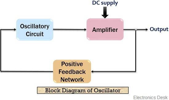
Here the feedback network is the frequency selective circuit. It is noteworthy here that the oscillatory circuit employed before the amplifier circuit in the above figure can be LC tank circuit, R-C network or quartz crystal.
The amplifier basically changes the dc voltage provided by the supply into ac power. This ac signal is then given to the tank circuit through a feedback path. Further, the oscillations of the tank circuit are fed to the amplifier.
Since the amplifier amplifies the applied input at its terminal. Thus, at the output of the amplifier, amplified oscillations are achieved because of the applied dc voltage.
As we know that we have employed a positive feedback circuit over here. The reason for this is that feedback provides a part of the output to the oscillatory circuit in the correct phase so as to have sustained oscillations.
Now, let’s move further in order to understand the detailed operation of an oscillator.
Circuit operation of an Oscillator
In the previous section, we got the idea about the basic working of an oscillator with the help of block diagram. So, in this section, we will get to know about the operation of the oscillator by circuit analysis.
The figure below represents the basic oscillator feedback circuit:
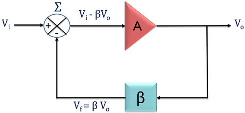
Suppose, Vi is the input applied at the terminal of the amplifier having gain A. Also, a feedback network is used. This feedback network has the feedback fraction β. The output of the amplifier is Vo and that of the feedback network is Vf.
Here β basically defines the fraction of output which is provided as feedback to the input.
Initially, Vi is applied at the terminal of the amplifier with gain A. So, at the output of the amplifier we get,
![]()
This voltage is then provided to the feedback network which is basically a resonant circuit in order to have the highest feedback at a frequency.
So, the signal achieved at the output of the feedback amplifier is given as,
![]()
Since, Vf = βVo and Vo = AVi
If the amplifier and feedback circuit introduces 0° phase shift. Then both feedback signal, as well as the input signal, will be in phase with each other.
Now, when the output of the feedback circuit is provided to the amplifier along with the input.
Then, the signal at the output of the amplifier will be given as,
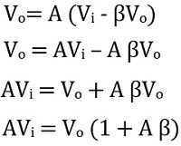
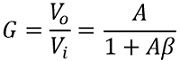
So, we can write, the closed loop gain of the oscillator with feedback,
Suppose, we provide only the output of the feedback circuit at the input of the amplifier and remove the originally applied input signal.
After the removal of Vi, the loop gain of the oscillator is responsible for sustained oscillations.
- If the open loop gain is less than one i.e., Aβ < 1. Then after some period of time, the output will die out. This is so because, here AβVi serves as input to the amplifier, so this will be less than Vi and Aβ will be less than unity.
Hence, each time after passing the loop the amplitude of the signal will get reduced. Resultantly, oscillations will die out.
- If loop gain is more than one i.e., Aβ > 1. Then it causes the output to get built up. Thus, each time on passing the loop, increase in the amplitude of the oscillations is noticed.
- Now, if the loop gain is equal to one i.e., Aβ = 1. Then it causes Vf to be equal to Vi. Thus at the output, the signal will be a continuous sinusoidal waveform. In this way, the input is itself provided by the circuit and hence a sinusoidal output is achieved.
It is to be noted here that, initially, the loop gain is always more than 1 in order to build up the oscillations. But, once a certain voltage is reached by the signal then the loop gain now becomes 1.
This is due to the non-linear behaviour of the feedback amplifier circuit.
What is Barkhausen Criteria?
Barkhausen criteria state the two conditions to achieve sustained oscillations. These are given below:
- The open loop gain which we have recently discussed must be slightly more than or equal to 1. This means Aβ ≥ 1.
- The overall phase shift of the circuit must be 0. So, that the input and output signal will be in phase with each other.
These two conditions will provide sustained oscillations at the output of the amplifier. This is termed as Barkhausen Criteria.
Significance of Oscillatory Circuit
Oscillatory circuit is formed by LC network, RC circuit or quartz crystal etc. In the figure here a tank circuit is represented by the parallel connection of an inductor and capacitor:
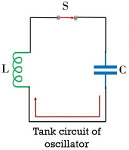
In the open switch condition, the operation of the circuit will not proceed. However, once the switch is closed, then the operation of the circuit starts.
When the switch gets closed then the capacitor in the circuit begins discharging. Due to discharging of the charged capacitor, electrons start moving through the circuit. The flow of electrons generates current in the circuit but in the direction opposite to the movement of electron flow.
Due to this flow of current through the inductor, flux linkage is noticed. This resultantly produces magnetic field near inductor. Thereby storing power/energy in the inductor as a magnetic field. This stored energy in the inductor generates emf.
Due to the generated emf, current will again begin to flow through the circuit. Thus, charges will flow and the capacitor will ultimately get charged and holds energy in the form of the electrostatic field.
This alternate charging and discharging of capacitor and inductor will produce continuous oscillations.
It is to be noted here that the circuit generates damped oscillations. The figure below shows the waveform in case of damped oscillations:
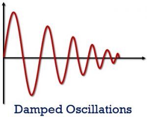
Here, we can see that the amplitude of the sinusoidal oscillations is not equal. This is due to the presence of losses in the inductor and capacitor.
The figure below shows the waveform for Undamped oscillations:
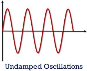
Basically, the oscillator is supposed to provide such oscillations but this does not happen exactly.
Frequency of the Oscillator circuit
It is also called as Resonant frequency. It is basically defined as the frequency of oscillations. Usually, the particular frequency at which the oscillator is set initially is not maintained over the entire cycle of oscillations.
This is so because, these resistor, inductor and capacitor show variation with the increase in circuit temperature.
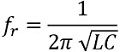
Therefore, there exists a formula for the resonant frequency of oscillator:
We know,![]()
and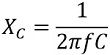
For resonance to occur
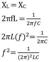
The expression for the resonant frequency of a tuned LC circuit
Advantages of Oscillator
- An oscillator is durable equipment. As it does not rotate and hence there are chances of fewer damages to get introduced.
- The oscillating frequency is easily adjustable.
- The frequency of oscillation exhibits stable behaviour.
- It is less noisy.
- It is a highly efficient device.
Applications of Oscillator
Oscillators are widely used in numerous circuits like in amplitude and frequency modulating circuits, in superheterodyne receivers etc. These are used to produce clock signals.