Half Wave and Full Wave Rectifiers are the two categories of rectifier circuits. The crucial difference between Half Wave and Full Wave Rectifier is that a half wave rectifier converts only one-half cycle of the ac input supplied into pulsating dc signal. As against a full wave, rectifier converts both halves of the applied input signal into pulsating dc.
Another major difference between the two is that the rectification efficiency of half wave rectifier is somewhat less as compared to the full wave rectifier.
Let’s have a look at the contents to be discussed under this article, then we will move further and discuss other important differences between the two.
Content: Half Wave Vs Full Wave Rectifier
Comparison Chart
| Parameters | Half Wave Rectifier | Full Wave Rectifier |
|---|---|---|
| Number of diodes used in circuit | 1 | 2 or 4 (It varies with the type of circuit) |
| Maximum efficiency for rectification | 40.6% | 81.2% |
| Basic ripple frequency | f (i.e., supply frequency provided) | 2f |
| Ripple factor | More | Less |
| Voltage regulation | Good | Better as compared to half wave rectifier |
| Transformer utilization factor | 0.287 | 0.693 |
| Peak inverse voltage (PIV) | Maximum value of supplied input | Twice the maximum value of supplied input |
| Peak factor | 2 | 1.414 |
| Form factor | 1.57 | 1.11 |
| Average current value | Imav/π | 2Imav/π |
| Transformer core saturation | Possible | Not posiible |
Definition of Half Wave Rectifier
A half wave rectifier is a circuit that passes only one half of the applied input signal and blocks the other. More clearly, we can say, that when positive half of the input is passed then negative half is blocked and vice-versa. Only one diode is used in the construction of half wave rectifier.
The figure below shows the circuit of half wave rectifier:
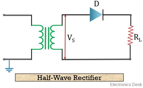
As we can see in the figure that it is composed of an ac source, a diode, a step-down transformer, and a resistor that serves as a load.
Now let us understand how a half wave rectifier circuit operates:
When positive half of the input ac signal is applied at the circuit, then the diode gets forward biased. As we are already familiar with the operation of a diode that in forward biased case it starts behaving as a closed switch. Due to this, it passes current or we can say it conducts.
It can be clearly seen in the figure that resistor or load is in series with the applied input voltage. Thus the current that flows through the diode will appear across the load. Hence we achieve positive half of the applied input signal at the output. When negative half of the ac input signal is applied then it makes the diode reverse biased. Due to which it acts as an open switch hence no current flows through it. Resultantly, no any output appears at the load.
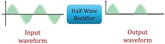
So, at the output of the half wave rectifier, we achieve a set of positive half cycles between which some constant negative voltage also appears.
The figure below represents the output achieved in the case of half wave rectifier:
Definition of Half Wave Rectifier
A full wave rectifier is a circuit that has the ability to pass both the halves of the applied input signal. In other words, the overall applied ac input signal is converted into pulsating dc by the full wave rectifier. A full wave rectifier circuit can be either a centre-tap full wave rectifier or a bridge rectifier circuit. Both operate in a little different manner. A centre-tap full wave rectifier circuit needs 2 diodes whereas a bridge rectifier circuit consists of 4 diodes.
The next figure shown below represents the circuit of a centre-tap full wave rectifier:
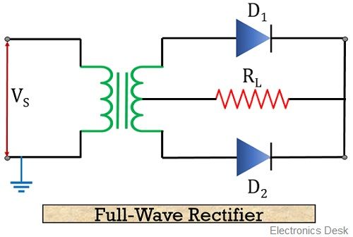
It consists of a step-down transformer along with 2 diodes connected with the resistor(load).
Let us now move further to understand the operation of full wave rectifier:
When positive half of the input is applied to the circuit then it causes diode D1 to gets forward bias thereby allowing the flow of current through it. Hence the signal appears at the load. However, at the same time this positive half reverse biases the diode D2. Thereby conduction does not take place through it. Hence no any output is achieved. But due to conduction of D1 positive half appears at the load of the circuit.
Moving further, when the negative half of the input is applied. Then diode D1 will come in reverse biased condition and conduction will not take place through it. Resultantly, no output is achieved at the load. But due to this negative half cycle, diode D2 will now be forward biased and now starts conduction. Due to which current flows through it and hence appears at the load.
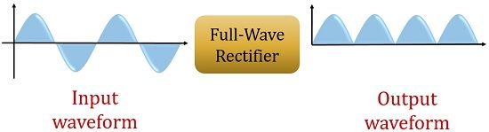
It is noteworthy here that the direction of the current that flows through the load is same in case of both the applied halves of the input signal. Hence, we achieve continuous positive half cycle at the output of full wave rectifier.
The figure below represents the output achieved in the case of full wave rectifier:
Key Differences between Half Wave and Full Wave Rectifier
- The factor that generates a key difference between half wave rectifier and full wave rectifier is that a half wave rectifier shows unidirectional nature and hence makes use of only one-half cycle of applied input. While the full wave rectifier shows bidirectional nature as both the halves of the input signal is utilized at the time of operation.
- A circuit of half wave rectifier requires only 1 diode. While 2 or even 4 diodes are also utilized in the circuit of full wave rectifier.
- The fundamental ripple frequency in case of half wave rectifier is f i.e., supplied input frequency (50 Hz). While it is twice the supplied frequency i.e., 2f (100 Hz) in case of full wave rectifiers.
- A half wave rectifier has good voltage regulation. However, full wave rectifiers provide better voltage regulation as compared to half wave rectifiers.
- The ripple factor in case of half wave rectifier is more in comparison to the full wave rectifier. For half-wave rectifier, it is about 1.21 but for full wave rectifier, it is 0.482.
- The peak inverse voltage in case of half wave rectifier is equivalent to the maximum value of applied input voltage. While peak inverse voltage of full wave rectifier is twice the maximum value of applied input voltage.
Conclusion
So, from the above discussion, we can conclude that both half wave and full wave rectifiers are used to transform ac into pulsating dc. Only the variation is the utilization of an applied input signal. However, pulsating dc output shows that some ac ripples are also present in it. So, it must be as small as possible. But the ac ripples in case of half wave rectifier is somewhat more as compared to full wave rectifier.
Thanks it was very helpful for me
Thank you SO much 😍🥰
I appreciate your contributions well organized and more understandable. Thanks
really helped me with my engineering work :)Thanks
Grt explanation