Definition: A full wave rectifier is a rectification circuit that is used to change the overall ac signal that is applied across its terminals into a pulsating dc form.
We know that rectification is nothing but the conversion of ac signal into dc. However, basically there exist two types of rectifiers, the first one is a half wave rectifier while the second one is a full wave rectifier which we will be going to discuss in this article.
A half wave rectifier changes only one half of the applied ac signal into pulsating dc. While, unlike half wave rectifiers, a full wave rectifier utilizes both the halves of the ac input signal for rectification.
Half-wave rectifiers are less efficient rectifiers as the dc output voltage is less in its case. Also, the ripple factor is more in case of half wave rectifiers. So, to overcome all these drawbacks associated with half wave rectifiers, full wave rectifiers were introduced.
A full-wave rectifier uses either 2 or 4 diodes in order to convert the applied ac signal into dc one. So, on the basis of the number of diodes used in the circuit and their arrangement, full wave rectifiers are classified as
In this section, we will separately discuss how the two circuits change an ac signal into a pulsating dc signal. So, let us first discuss the centre-tap full wave rectifier.
Centre-Tap Full-Wave Rectifier
The figure below shows the circuit representation of a centre-tapped full wave rectifier: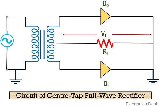
Here, we can see that the rectifier circuitry is composed of a centre-tapped transformer, whose secondary winding forms a connection with the anodes of the two diodes D0 and D1. While the primary winding is provided with the ac input supply.
The cathode of the two diodes are connected together with a load resistance RL and again with the centre of secondary of the transformer.
Let us proceed further to understand the operation of the centre-tap full-wave rectifier.
Working of Centre-tap Full-Wave Rectifier
As we know that this type of full wave rectifier uses two diodes in its circuits. So, when the two halves of the ac input cycle are provided to the diodes, then the two changes both the halves of the ac signal into pulsating dc.
Thus when the positive half of the ac signal is provided to the primary winding of the transformer then it steps down the signal and provides it to the secondary winding. This positive half of the ac signal, forward biases the diode D0 but reverse biases the diode D1.
Due to this D0 acts as a closed switch and current starts flowing in the upper half of the circuit through RL.
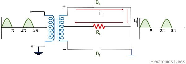 This provides one half of signal at the output of the rectifier.
Further when the negative half of the ac input signal is provided to the diode then this second half reverse biases the diode D0 but forward biases the diode D1. So, at this time, D1 acts as a closed switch.
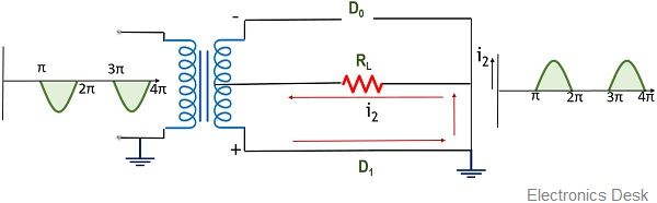 Thereby allowing current to flow at the lower region through the load resistance RL.
As we can see in the figure above that in both cases, the direction of flow of current is the same.
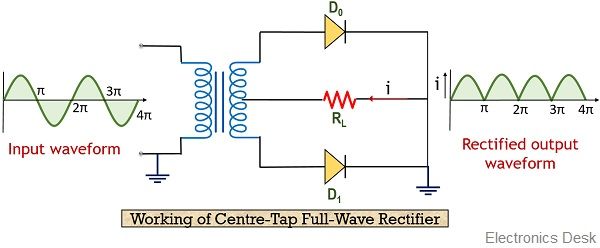
Thus, combinely at the output, we achieve continuous positive half cycle.
Bridge Full-Wave Rectifier
The figure given below shows the circuit representation of a bridge type full wave rectifier:
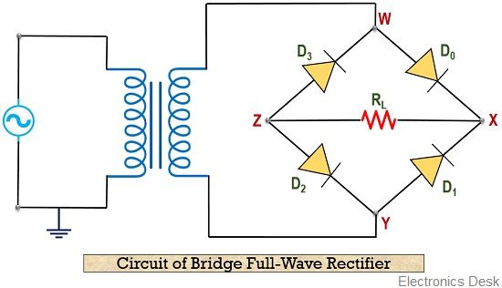
As we have already discussed that a bridge rectifier is composed of 4 diodes. The circuit representation is called so because the diodes are connected together in Wheatstone bridge configuration.
As we can see that this connection forms 4 junctions namely, W, X, Y and Z. So, junction W and Y are connected to the secondary winding of the transformer. While the junction X and Z are connected with the load RL.
Let us move further to know the operation of the bridge full wave rectifier.
Working of Bridge Full-Wave Rectifier
We have already seen the circuit showing the bridge configuration of the full-wave rectifier.
So, when one half of the ac signal is provided then out of 4 only 2 will get forward biased while the other 2 gets reverse biased. In a similar way when another half of the signal is supplied the other 2 diodes in the circuit gets forward biased.
Let us consider that the positive half of the ac input signal is provided to the circuit. Then the positive half of the signal, forward biases the diode D0 and D2.
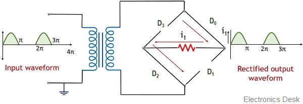
This forward connection allows forward current to flow through the load RL thereby generating a signal at the output of the rectifier.
Further, when negative half of the signal is applied then it forward biases the diode D1 and D3. Due to this forward connection, these 2 diodes act as a closed switch and current starts flowing through the load resistance RL.
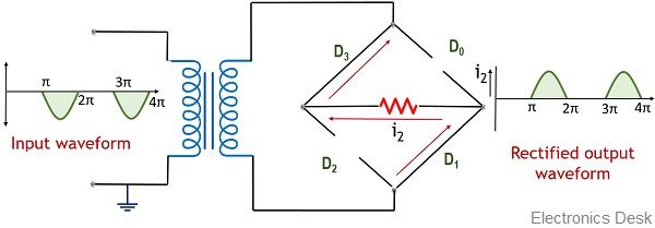
As we can see in the figure that the direction of flow of current through the load is the same for both the halves.
Thus at the output of the circuit, a continuous positive half signal is obtained.
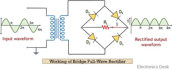
In this way, a full-wave rectifier operates to provide a pulsating dc signal at its output.
Analysis of Full-Wave Rectifier circuit
These are the following factors that are to be analyzed here:
Peak Current
Suppose the voltage applied at the input of the rectifier is
Vs = Vs max sin ωt
We have already discussed the two current flows in case of 2 different half cycles of the input, so
For positive half of input,
i1 = Imax sin ωt and i2 = 0
For negative half of input,
i1 = 0 and i2 = Imax sin ωt
Thus the total current at the load for overall ac input signal will be
i = i1 + i2 = Imax sin ωt
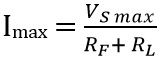
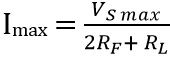
And the peak value of current across the load
For centre-tap rectifier is,
For bridge rectifier is,
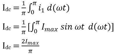
Output Current
As we already know that current through the load is the same for both the cycles of the ac signal thus, the dc output current can be given as
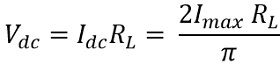
DC output voltage
The average dc voltage is given as
RMS Current
The rms current through the load RL is given as
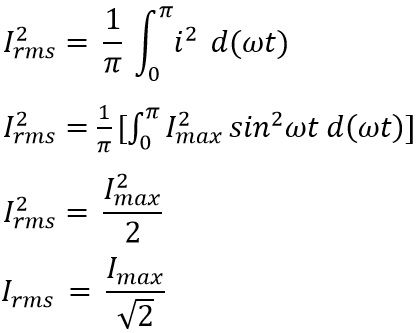
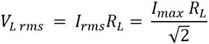
RMS Output Voltage
The rms value of a voltage across the load is given as
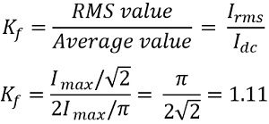
Form factor
The form factor is the ratio of rms value to the dc output value of current. It is given as
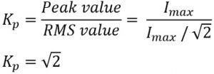
Peak factor
It is the ratio of the peak value of current to the rms value of current
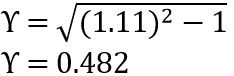
Ripple factor
The ripple factor of a full wave rectifier is given as
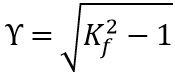
Putting the value of Kf in the above equation
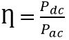
Rectification Efficiency
We have already discussed that the rectification efficiency is the ratio of dc power to the ac power.
Since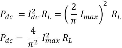
Also, ac input power
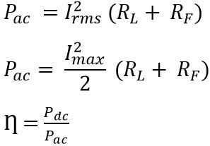
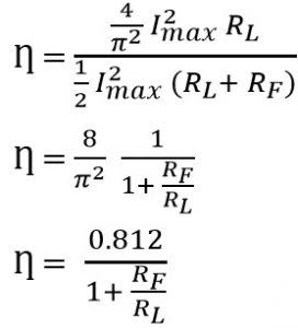
Substituting the values in the above equation
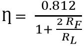
For bridge rectifier,
Advantages of Full-Wave Rectifier
- It provides better rectification efficiency than a half-wave rectifier.
- Less ripple component is present at the output.
- The achieved output voltage is large.
Disadvantages of Full-Wave Rectifier
- The circuit of full wave rectifier is complex.
- It is an expensive circuit due to more components.
This is all about the circuit and working of a full wave rectifier.
Very nice explanation. I appreciate this article. Thank you for updating this.