Definition: A Half-Wave Rectifier is a device that converts only one half of the applied ac signal into pulsating dc. The other half of the applied ac signal gets suppressed by the rectifier circuit.
A half wave rectifier circuit uses only a single diode, due to the unidirectional current flow property of the diode.
We know that rectifier is basically a device that is used to change an ac signal into a pulsating dc form. But how this happens by making use of diodes?
We are aware of the fact that a diode exhibits the property of conducting current in forward direction only by blocking the conduction in reverse direction.
Also, when resistance is connected in series with the diode, then the unidirectional voltage will appear across the resistance.
Thereby changing ac signal into dc. So, this property is utilized by the rectifiers for the purpose of signal rectification.
Rectifier circuits can be composed of either 1, 2 or 4 diodes. A half wave rectifier needs only a single diode. While the full wave rectifier circuit needs 2 or 4 diodes depending on the type of circuit.
Half-Wave Rectifier Circuit
The figure below represents the circuit diagram of a half-wave rectifier:
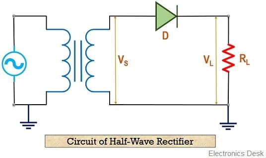
Here, the figure shows the circuit of the half-wave rectifier, consisting of a pn junction semiconductor diode and a load resistance RL in series with it. The diode and resistance form series connection with the secondary winding of the step-down transformer. While the primary is connected with the ac source.
Now, let’s proceed further and understand how a half wave rectifier operates.
Working of Half-Wave Rectifier
The ac source provides ac voltage to the primary winding of the step-down transformer. This reduces the high applied ac voltage to a low-value ac value.
So, this ac voltage is allowed to flow through the rectifier circuit. But both the halves react differently when passed through the circuit.
Firstly let us understand the case when the positive half of the input signal is provided to the circuit. The applied positive half of the input signal forward biases the diode.
As p side of the diode is connected to positive polarity and n side is connected to the negative polarity. Due to this the diode shows a closed switch structure and allows the current to flow through the circuit.
This is shown in the figure below:
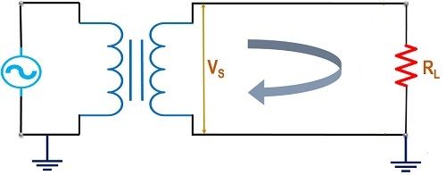
Resultantly, the overall applied voltage appears across the load resistance. As the diode is assumed to be an ideal diode.
Further when the negative half of the ac input is applied to the circuit. Then due to this, the diode comes in reverse biased condition. Due to this, the diode starts acting as an open switch, thereby restricting the path for the flow of current in the circuit.
This is shown in the figure below:
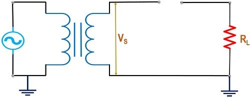
Resultantly, for the negative half of the voltage, no power appears at the load.
Hence at the load of the half wave rectifier circuit, a series of positive half of the applied input voltage is achieved.
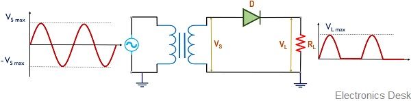
Also, it is clear from the above figure that the output is pulsating dc despite being steady dc.
So, to eliminate these ripple component (ac part), filter units are employed that gives constant dc signal at the output.
Analysis of Half-Wave Rectifier
The factors that are to be analyzed in this section are as follows:
Peak Inverse Voltage: It is abbreviated as PIV. It the maximum voltage that can be handled by the diode when it is reverse biased.
As in reverse bias no current flow through the circuit, thus the applied reverse voltage appears across the diode.
Hence, for the half-wave rectifier, the maximum applied voltage is the PIV thus,
PIV = VS max
Peak Current: Peak current is defined as the maximum current that flows through the rectifier circuit.
The sinusoidal applied input voltage is given as
VS = VS max sin ωt
And the current flowing through the circuit,
i = Imax sin ωt for 0 ≤ ωt ≤ π
i = 0 for π ≤ ωt ≤ 2π
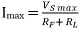
Then the maximum current flowing through the diode is given as
DC output current: The dc output current of the half-wave rectifier is given as
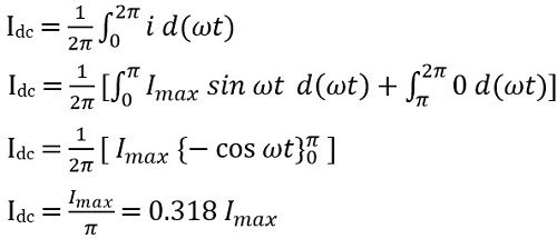
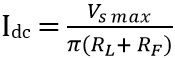
On putting the value of Imax in above equation we get
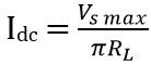
If RL >> RF
DC output voltage: Average value of the voltage at the load is given as
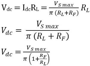
If RL >> RF
Then 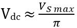
RMS value of current: The RMS current flowing through the diode
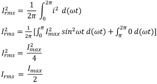
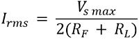
Putting the value of Imax in the above equation
Output RMS voltage: Value of RMS voltage across the load is given as
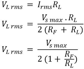
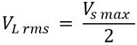
If RL >> RF
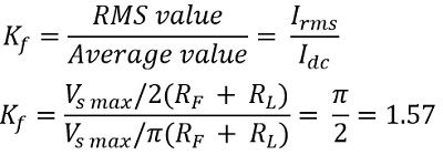
Form factor: It is defined as the ratio of RMS current to the dc output current. It is given as
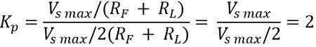
Peak factor: It is defined as the ratio of peak current to the RMS current. And is given by
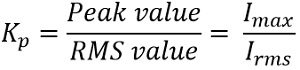
So, we will have
Output Frequency: The output frequency is equivalent to the input frequency for a half wave rectifier.
fout = fin
Ripple factor: The pulsating dc output of the half wave rectifier, has some ac components contained in it. These ac components are known as ripples.
These ripples are basically undesirable and the value of ripple current must be as small as possible in order to have high efficiency.
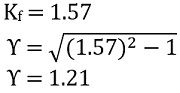
The ripple factor is given as,
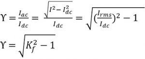
We know,
Rectification Efficiency: It is the ratio of dc output power to the ac input applied power.

Advantages of Half-Wave Rectifier
- It is inexpensive
- The circuit is quite simple.
Disadvantages of Half-Wave Rectifier
- A half wave rectifier offers high ripple factor thus is proved as a disadvantageous factor.
- Due to low rectification efficiency, half wave rectifiers are considered to be less efficient.
- The transformer utilization factor is also low in case of half wave rectifier.
This is all about the circuit and working of half wave rectifier.