Definition: 8085 is an 8-bit microprocessor as it operates on 8 bits at a time and is created with N-MOS technology. This microprocessor exhibits some unique characteristics and this is the reason it still holds popularity among the microprocessors.
Basically, 8085 was the first commercially successful microprocessor by Intel. As some of the architectural drawbacks associated with 8080 was also eliminated by 8085.
The size of the data bus of 8085 is 8 bits while that of the address bus is 16. Therefore, can address 64 KB (i.e., 216) memory. Also, as it can perform 8-bit operation thus the size of ALU is also 8-bit.
It also provides operational advantages, as 8085 needs a single +5V supply with only one clock single of width 320 ns. While 8080 requires 3 power supply lines and 2 clock signals of 500 ns.
Architecture of 8085 Microprocessor
The architecture of 8085 microprocessor provides the idea about what are the operations to be executed and how these are performed.
It can perform operations that are given below:
- Operates on and stores 8-bit data.
- It executes arithmetic and logic operations.
- 8085 also sequences the instructions to be executed.
- Stores data temporarily.
However, in order to perform all such operations, the processor needs a control unit, arithmetic logic unit, registers, buses etc.
We have already discussed how CU, ALU and buses function in a microprocessor. Here, in this article, we will discuss the detailed architecture of 8085 microprocessor and how it operates.
The figure below represents the architectural representation of 8085 microprocessor:
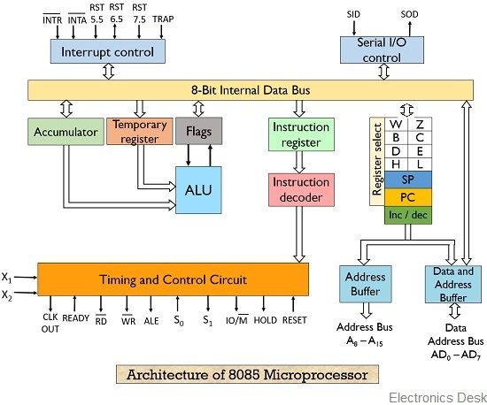
Functional Units of 8085:
1. Registers: These are nothing but set of flip flops. These are basically used to hold (store) the data.
General purpose registers– 8085 microprocessors contain 6 general purpose registers that are present inside the microprocessor and stores 8-bit data in order to execute a program.
These general purpose registers are B, C, D, E, H and L. These registers can be combined to form pairs – BC, DE and HL in order to execute the 16-bit operation.
These are programmable registers, that means these registers are accessed by the programmer to insert and transfer the data by making use of instructions.
Temporary registers: These registers are used by the ALU to store the data on temporary basis and these are not accessed by the programmer. These are of 2 types:
- Temporary data register – It is an 8-bit register that holds the operand and provides it to the ALU for program execution. Also, the immediate results are stored by the ALU in this register.
- W and Z register – These registers are also used to hold the temporary values. It is used by the control section of the microprocessor so as to store the data during operations.
2. Program Counter (PC): It is basically a special purpose register that is used to store the memory location of the instruction to be performed. As it is clear that in order to fetch an instruction from the memory the microprocessor needs to know about its address.
It is a 16-bit register as it stores address. This register is used by the microprocessor to line up the instructions that are to be executed in a sequential manner.
It functions in such a way that it fetches the opcode from one memory location and simultaneously get incremented by the next memory location. Thus, it provides sequencing of the program to be executed.
3. Stack Pointer (SP): It is also a 16-bit register and is a part of memory. The data is stored in the stack in serial format and stack pointer generally stores the address of the last data element stored in the stack. Thus the stack is based on LIFO.
Whenever a new data is added in the stack, then the stack pointer starts pointing towards the very next memory location.
As against, when a data element is removed from the stack, then the stack pointer points to previous occupied memory location.
4. Accumulator: It is an 8-bit register that stores the result of the operation performed by the ALU. It is also known as register A.
5. Flags: Flag register basically holds the status of the current result generated by the ALU and not the actually generated result. Thus we can say it is used to test the data conditions.
8085 has 5 flags that shows 5 different data conditions. These are carry, sign, zero, parity and auxiliary carry flags.
However, the mostly used are: sign, carry and zero.
Working of 8085 Microprocessor
Now after having an idea about the functional units of the 8085 microprocessor, let us proceed further to understand the operation of the 8085 microprocessor.
We already know that the function of a microprocessor is to execute instructions. Also, in order to execute an instruction, it first needs to be fetched then decoded and then executed. And in order to fetch an instruction, firstly the address of the instruction must be known.
The address of the instruction is present in the program counter. This address is then placed on the 16-bit address bus and is then forwarded towards the memory. From the memory, the instruction present at that particular memory location is fetched through the 8-bit data bus.
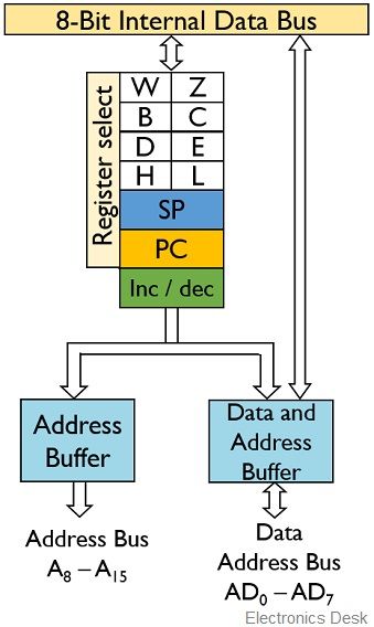
Here, in the above figure, we can clearly see that we have combinely used data bus and address bus so as to reduce the number of lines. As we know that at a particular time the processor will access either the data bus or the address bus.
Further when the instruction is fetched from the memory, then through internal buses the instruction is provided to the instruction register. At this particular point of time fetching the instruction from the memory is over.
Now, it’s time for the processor to decode the instruction. So, it is then fed to the instruction decoder.
We already have the idea that both data and instruction in the memory is stored in the form of an opcode. So, the fetched opcode is analyzed by the instruction decoder present inside the processor in order to execute the instruction.
But, a noteworthy point over here is that, after an instruction is fetched from the memory, then PC increments itself thereby providing the address location of the next instruction. As PC does not play any role in decoding and executing.
However, after execution of first instruction, the next is fetched form the memory.
Now, this is all about fetching and decoding, now what about the execution of the instruction.
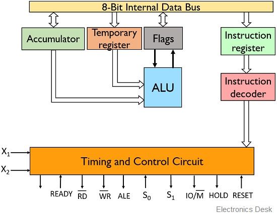
In the above figure, we can see the timing and control circuit. This circuit basically sends the control signals to the various units of the microprocessor to execute the instruction.
Suppose, the instruction is ADD A and B. This simply tells the ALU to add the data present in B register with the data present in accumulator i.e., A register. But, in 8085 the decoded instruction is simply ADD B. So, automatically, the ALU adds the value present in the accumulator with the data in register B.
Also, in 8085 the outcome of the operation is stored register A which is nothing but an accumulator.
Further when an instruction ADD C is decoded by the 8085, then data at C register is added to the data present in register A and is stored at register A. Due to such cumulative action, register A is termed as an accumulator.
Basically, the timing and control circuit timely sends the signals to the accumulator to release its value for proceeding execution. Also, this timing and control circuit sends signals to the register select that tells it to choose the particular register.
Once the data is fetched from a particular register then it is stored in the temporary register and it is used by the ALU. It is to be kept in mind that a programmer can only access the general purpose register as the temporary register is used by the processor to hold the 2nd operand of the operation.
Now, once the operation is executed, then the result is fed to the accumulator through the data bus. But a flag register is also present that holds the status of the result present at the accumulator.
As we have also discussed in the functional unit that a flag register holds a sign, carry etc. related information of the generated result.
After every instruction execution performed by the ALU, the status of the flag register gets changed. So, ALU produces the result and its status simultaneously after each operation.
As we have already discussed that W and Z are the temporary registers but these are not accessed by the programmer as both are used by the processor to hold the temporary value stored by it.
So, this is all about the block diagram and working of 8085 microprocessor.
Applications of 8085 microprocessor
8085 finds its major applications in programmable calculators as well as in numerical control and environment monitoring systems. These are also used in switching, banking and financial systems.
Grt content