Interrupts are the signals that are generally produced by the devices externally connected to the microprocessor, requesting for the services. Whenever an interrupt request is generated in the system then it must not be neglected and be acknowledged as soon as possible.
Basically whenever an interrupt is generated then the microprocessor suspends its current execution and switches to service the interrupt that is requested by the external device. In order to service the interrupt, the processor executes a routine which is called the interrupt service routine. So, after the execution of interrupt service routine (ISR) the processor, resumes the original program that was under operation before the generation of the interrupt. Sometimes some special instructions inside the processor generate interrupts. Those are handled by the processor internally.
Suppose the processor is executing an instruction and a keyboard key is pressed. Then at this time, the processor gets to know that the external device keyword is requesting its services.
So, if the processor checks for the priority of the generated interrupt and if the generated interrupt holds high priority then the processor switches to execute the ISR by storing the address of the current program in the stack. This is done so that after the execution of ISR, the processor can switch back to the main program.
In this article, we will discuss the interrupts of 8085 microprocessor.
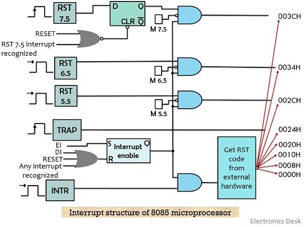
Interrupt Structure of 8085 Microprocessor
 Initially, there was an approach called polling used in the microprocessor. Now the question arises,
What is Polling?
In polling or polled approach, the software inside the microprocessor checks each peripheral device according to the priority that whether any one of them needs the processor services.
In polling, a program inside the processor checks the I/O ports A, B and C for the need of service. As we have already said that the ports are sequentially checked on the basis of priority. So, one after the other each of the peripheral devices are checked. But the priority assigned to each of the I/O devices can be changed and thus the polling routine.
However, this will lead to unnecessary processor utilization when no external request for the processor is generated. Thereby causing a great reduction in the overall throughput of the system. So, to have an efficient system, another desirable technique was taken into consideration by which whenever a device needs service of the processor, then it will send a signal to it in order to request for its services. These signals are nothing but the interrupts.
Interrupts in 8085
8085 supports multilevel interrupts. So, the interrupts are classified as:
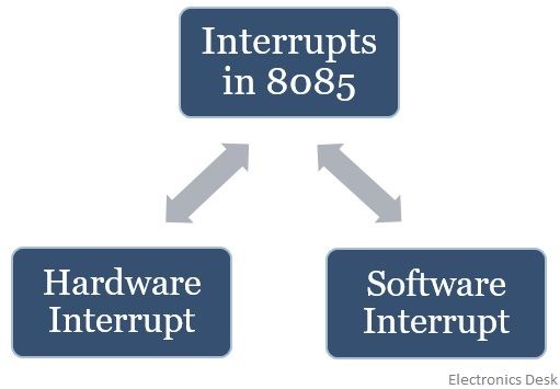
- Hardware Interrupt: These interrupts are basically associated with peripheral devices generated at the time of data transfer between I/O device and microprocessor. An external device generates interrupt by placing an interrupt signal over the pins of the microprocessor.
The 8085 microprocessor holds some pin, which gets enabled whenever the peripheral devices interrupt the main program for an I/O operation. - Software Interrupt: Sometimes the execution of an instruction generates interrupt in the microprocessor. So, in case of the internally generated interrupt, the processor suspends the current execution and switches to handle the interrupt. But once the ISR is executed the processor returns to the main program.
Let us now move further and understand the different types of hardware and software interrupts.
Hardware Interrupts
The hardware interrupts of 8085 are as follows:
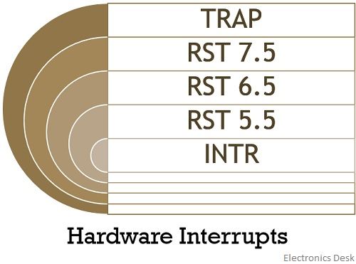
Out of the 5 hardware interrupts, only INTR is a non-vectored interrupt rest other are vectored interrupt.
Vectored interrupts are those interrupts whose service routine address is known to be a processor. So, once a vectored interrupt is generated then the processor automatically suspends its main program and switches to the vector location. While the INTR is non-vectored interrupt that means the processor is unknown about the memory location from where the interrupt is generated and is needed to be serviced. So, in such a case the interrupt generating device sends the address of the location where the interrupt is to be serviced.
Let us discuss the different hardware interrupts:
TRAP: TRAP is the highest priority interrupt and is non-maskable in nature. As this interrupt is non-maskable thus cannot be masked (i.e., rejected or delayed) under software control by the processor. This interrupt is edge and level triggered. Thus the signal at this pin must be high and remain enabled until it is acknowledged by the processor.
Due to non-maskable nature, a TRAP signal at the pin can be cleared only in two ways:
- The first is resetting of the processor by providing a low signal at the RESET pin.
- The second is acknowledging the high TRAP signal.
So, basically whenever a high signal is received at the TRAP pin of 8085 then the processor generates an acknowledging signal by clearing the flip flops. So, after this interrupt is acknowledged then the processor stores the return address of the program in current execution in the stack. Also at the same time, the Program counter is loaded with the fixed vectored address of the TRAP interrupt in order to execute the ISR operation.
RST 7.5: This interrupt holds the second-highest priority among these interrupts and is maskable in nature. If the mask bit of the interrupt is low, then this shows that the processor is not masking the interrupt. So further the processor loads the address of the current operation in the stack and loads the vector address of RST 7.5 i.e., 003CH onto the PC. Thus, 8085 starts executing the instruction in the memory location in order to service the routine.
RST 6.5 and RST 5.5: These two are level-triggered interrupts and can be masked by the processor. The RST 6.5 and RST 5.5 holds a third and fourth level of priority respectively.
Like the above-discussed interrupts, whenever these two interrupts are generated then the processor loads the PC with the respective vector address after suspending the current execution.
INTR: It is maskable interrupt but we have already discussed that it is a non-vectored interrupt. And so whenever an INTR signal is received by the processor then the acknowledgement INTA is sent by the processor to the requesting device by which it asks for the address for the interrupt service routine. Once the external device provides the address of ISR to the processor then it loads the address in stack after it suspends the main program. Among all the hardware interrupts, INTR is the lowest priority interrupt.
Software Interrupts
There are total 8 software interrupts present in 8085 i.e., from RST 0 to RST 7 :
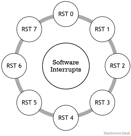 Basically whenever a software interrupt is generated then its vector address is calculated by:
Vector Address = Interrupt number × 8
Suppose we have to calculate vector address of RST 4 then, it will be
4 × 8 = 32 = 20H
Thus 0020H will be the vector address of RST 4
So, this is all about the interrupts of 8085 microprocessor.