The Intel 8279 is a keyboard/display controller that interfaces keyboard and display devices with the microprocessor-based system. Through the use of this controller, processor utilization reduces in correspondence to time-consuming tasks such as keyboard scanning and display refreshing.
Basically, it is a general-purpose controller that performs the function of driving the display unit as well as interfacing the keyboard and the CPU simultaneously.
Content: Keyboard/Display Controller – 8279
Introduction
Intel’s 8279 is a dedicated controller designed by Intel that offers simultaneous keyboard and display operations. It provides interfacing for 64-contact keys that are arranged in 8*8 matrix format. Also, through 8279 multiplexed interfacing can be obtained for 7-segment LEDs as well as other popular display devices.
It has a display RAM of 16*8 matrix, however; the arrangement can be organized in dual 16*4 RAM. The RAM is loaded by the CPU however, once data loading is done, the 8279 performs data displaying and refreshing functions.
It works in a way that the keyboard display interface keeps the keyboard under scanning in order to check if any key is pressed. If a pressed key is detected, then the keycode of the pressed key is sent to the CPU. Also, after the operation, the data which the CPU forwards it, is transmitted to the display device. These two operations take place within the system in a synchronized manner without disturbing the other ongoing operations of the CPU.
Methods of Interfacing Keyboard with CPU
Mainly there are two ways by which the keyboard can be interfaced with the CPU, these are as follows:
- Interrupt Mode: In this mode of operation, the CPU continues to perform its original task until and unless any request is generated to that a key is pressed and is required to be serviced.
- Polled Mode: In the polled mode of operation the CPU itself checks for any pressed key in a periodic manner by reading the flags of 8279. So, in this case whenever the CPU gets a signal that shows the pressed key then the requested service is served.
There is a 40 pin IC of 8279 which exists in the Dual In-line Package (DIP).
Block Diagram of 8279
The functional block diagram of the Intel 8279 keyboard/display controller is shown below:
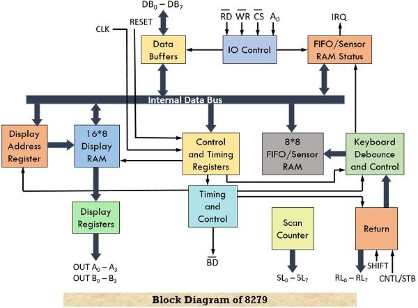
Let us understand the operation of this architecture by considering its 4 separate sections.
1. Keyboard Section: This section is composed of Return Buffer and Keyboard Debounce and Control. It holds the 8 return lines denoted by RL0 to RL7 that forms the column of the keyboard matrix. Shift and Control/Strobe are the two additional inputs provided to this unit.
The two operating modes are 2-key lockout and N-key rollover. In the 2-key lockout mode of operation, if two keys are pressed at the same time then the first recognized key will be considered by the system. While N-key rollover mode, whenever it is found that two keys are pressed at the same time then key codes of both of them get stored with the FIFO and are further serviced.
It has 8*8 FIFO RAM that works on the First–In–First–Out approach and can store 8 keycodes (code of pressed key) at a time in a sequential manner. The status of two additional input keys i.e., shift and control are also stored within FIFO RAM.
In scan keyboard mode, 8 keycodes are stored and anytime whenever an entry is made in the FIFO RAM then 8279 generates an interrupt signal that tells the processor to perform FIFO read operation till the time everything within FIFO is serviced. While in sensor matrix mode, the FIFO RAM holds the condition of 64 switches within it regarding whether these are open or closed. Whenever the condition of any switch is changed then 8279 generates an interrupt request for the processor.
2. Display Section: This section is constituted by display address registers and display RAM. This section contains 8 output lines i.e., A0-A3 and B0-B3 and these are connected to the 7-segment LEDs. There is a 16*8 display RAM and the processor simply performs read and write operations within this RAM.
The display address registers contain the address of that word on which the processor is currently performing the read/write operation.
3. Scan Section: The scan counter and four scan lines (SL0 to SL3) are part of this section. There are two modes of scan counter namely, encode and decode. In encode mode, a binary count will be obtained as the output of scan lines and this requires external decoding to give rise to decoded output. These output scan lines are the same for the keyboard and display and 4 scan lines can drive up to 16 displays.
However, in decode scan mode, internal decoding is performed that will provide a decoded 1 out of 4 scan lines and thus can drive up to 4 displays. Through scan lines, rows of the matrix keyboard are formed, and also it forms the connection to the drivers of the display unit.
4. CPU Interface Section: This section is composed of I/O control and Data Buffers along with Timing and Control Registers. The timing and control unit is also a part of this unit. This section is responsible for data transfer between 8279 and the CPU and hence consists of bidirectional data lines DB0 to DB7.
There are two internal addresses whose specified value i.e., either 0 or 1 makes the selection for either data buffer or control register. Here we have pins A0, CS, RD, and WR that are used for command, status, read and write operations. The IRQ is an interrupt request line that is specified for data transfer that is associated with generated interrupt requests.
It operates on an internal clock frequency of 100 kHz. The RESET signal provided to the 8279 is responsible for setting its 16-character display. The control and timing register holds the modes and operating conditions which program the CPU.
Operating Modes of 8279
Mainly, the operating modes of 8279 is classified as:
Input Modes
The input which is provided by the keyboard to the system specifies the input mode. This mode is classified into the following categories:
- Scanned Keyboard Mode: In this operating mode, the key matrix is interfaced with either encoded or decoded scan. In encoded scan, 8*8 keyboard is interfaced while in the decoded scan, 4*8 keyboard is interfaced. The keycodes are stored in the FIFO RAM.
- Scanned Sensor Matrix: This helps in interfacing the sensor array with 8279 by making use of an encoder or decoder scan. Similar to scanner keyboard mode, 8*8 sensor matrix for encoder scan and 4*8 sensor matrix interfacing for decoder scan.
- Strobed Input: This mode of operation, if control is not offered by the processor and the control line shows low signal then the data present on the return lines is stored in FIFO RAM byte by byte.
Output Modes
This mode is also known as a display mode. It is further classified into two modes. This mode helps in selecting the display options.
- Display Scan: The 8279 generates 8 or 16 characters multiplexed displays that are organized in either dual 4-bit or single 8-bit display units.
- Display Entry: The data which gets displayed can be either displayed starting from either the right side or left side.
Display Modes
This mode is associated with data display and has two further classifications.
- Left Entry Mode: It is also known as typewriter mode. In this, the first type of character is present at the left-most position while further incoming characters appear successively towards the right. This means data begins to appear from the left side of the display unit. So, the bit value at address 0 in the display RAM will appear at the left-most position whereas the bit value at address 15 will appear at the right-most position.
- Right entry Mode: This mode is also known as calculator mode. This is so because in the calculator the first entered character appears at the rightmost position and then successively when a new character has entered the position of the former one is shifted towards the left. Thus, in this mode, the first entry will appear at the rightmost position but as soon as a new entry is made then the previous one will get shifted towards the left by one and the present entry will take the rightmost position.
Hence in this way, keyboard/display controller 8279 operates.