We know that instructions are the binary commands used for the execution of any operation. In the previous article, we have discussed the instruction set of the 8085 microprocessor. Here in this article, we will discuss the instruction set supported by the 8086 microprocessor.
8086 supports various instructions including those supported by 8085. However, 8086 supports some additional instructions.
So, let us move further and understand the various instructions supported by the 8086 microprocessor.
Instruction set of 8086 microprocessor
The instruction set in 8086 microprocessor are classified as follows:
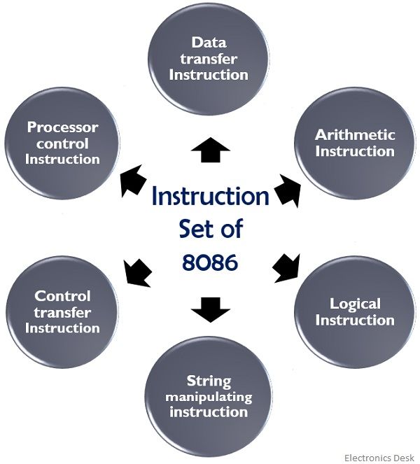
Let us now understand each type of instructions in detail.
Data Transfer Instruction
This group includes the instructions used for moving the data from one place to another. In data transfer group of instructions data or address can be transferred to either register, memory or I/O ports.
In order to accomplish any transfer, the source and destination must be known. So, these instructions involve two operands i.e., the source and the destination. The size of the operand must be the same.
The source holds either the immediate data, register or memory location. While the destination holds either the address of any memory location or register.
The various data transfer instructions are as follows:![]()
The data present in register 1 is transferred to register 2 or memory location given in the operand.
![]()
The data present in the memory is transferred to register 2.![]()
The immediate data is present in the operand is transferred to the memory location or the given register.
![]()
If the data in the memory is of 8-bit, then it is transferred to the lower address bit of the accumulator. And if the data is of 16-bit then it is transferred to the higher-order address of the accumulator.![]()
If AL is present as the operand, then 8-bit data at the accumulator is transferred to the memory. While in the case of AX, 16-bit data at the accumulator is transferred.
![]()
It allows the transfer of 16-bit data present in the memory or register present as an operand to the stack memory. This stack memory is generated when SP is decremented by 2.

The data present in the stack memory is transferred to either 16-bit register or memory location given in the operand and SP gets incremented by 2.
![]()
It allows the exchange of data between two registers or a register to memory location.
![]()
The data present in the input port is transferred to accumulator and its address is present in the DX register given in the operand.
![]()
The data of the input port is moved to the accumulator whose memory address is given in the instruction.
![]()
The data in the accumulator is moved to the output port whose address is specified in the DX register.
![]()
The data in the accumulator is moved to the port whose address is given in the instruction.
![]()
This instruction loads the register with the effective address of the memory location.

The data is in the first two memory location is moved to the register and from the next two memory locations is moved to DS register.

The lower byte of the data of the flag register is moved to the higher byte register of the accumulator.

It moves the data in the higher byte of flag register to the lower byte flag register.
Arithmetic Instructions
These instructions are used in order to execute arithmetic instructions like addition, subtraction, multiplication, division, increment or decrement.
The flags of the 8086 microprocessor are altered when arithmetic and logical instructions are executed. Basically, the status of the result of the operations is reflected by the flag.
![]()
The data in the two registers are added and output is stored in register 2.
![]()
The immediate data in the operand is added with the data present in the register and the result is stored in that particular register.
![]()
This instruction adds the data given in the operand with the data in the accumulator and the result is loaded in the accumulator.
![]()
The data in the two registers are added along with the bit of the carry flag. And the result is stored in register 2.
![]()
The data in the operand is added with the data in the memory location with the carry flag. And the outcome of the operation is stored in the memory.
![]()
The immediate data is added with the accumulator’s content and is stored in the accumulator.

When two ASCII data are added then this instruction is used for the conversion of the result in the accumulator in order to perform correction of unpacked BCD.
![]()
When two packed BCD data are added then executing this instruction will change the result in the accumulator to packed BCD data.
![]()
The data of the register 1 is subtracted from register 2 and the result is stored in register 2.
![]()
The immediate data in the operand is subtracted from the data in the memory and memory stores the result of the operation.
![]()
The immediate data is subtracted from the data in the accumulator and the outcome is stored by the accumulator.
![]()
The register 2 holds the result of subtraction of data in register 1 and carry bit from the data in the register 2.
![]()
The immediate data and a carry bit are subtracted from the data in the register and the register in the operand holds the result of the operation.

The immediate data and carry bit is subtracted from the data in the accumulator and the accumulator itself holds the result of the subtraction.

When the subtraction of ASCII data is performed then this instruction converts the results of the accumulator to perform correction of unpacked BCD.
![]()
The unsigned data in the register is multiplied with the unsigned data in the accumulator and the AX register holds result in 8-bit operation and AX and DX stores the result in 16-bit operation.

The signed data in the register is multiplied with the signed data present in the accumulator and the outcome of the operation is stored in AX and DX registers.

The outcome of multiplication of unpacked BCD data is a binary value stored in the AX register. So, this instruction is used for the conversion of binary data into unpacked BCD.

The unsigned binary data in the accumulator is divided by the unsigned binary data in the register. The AL register stores the quotient and AH register stores the remainder.

This instruction generates the 2’s complement of the data present in the register or memory. Simply put changes the sign of the data.
![]()
The data of the register or memory specified in the operand is incremented by 1.

The data in the specified register or memory location is decremented by 1.
The status of the flag register is modified by comparing the data of the two registers without altering the data of the registers. Subtraction is used for comparison.

It also performs comparison operation but this time the comparison is performed between the data in register and memory.
![]()
The data at the accumulator is compared with the immediate data given in the operand to modify the flag.
Logical Instructions
These instructions perform operations like AND, OR, complement, shift and rotate on the binary data. The outcome of the operation executed by logical instructions is represented as the status of flag register.

AND operation over each bit of two registers is performed and register 2 stores the result.
![]()
The immediate data is ANDed with the data present in the accumulator. And the accumulator stores the result.

The data in register 1 is logically ORed with the data in memory and the result is stored in that memory location.
![]()
The immediate data in the operand is ORed with the data in the accumulator. And AL and AX store the result of the operation.
![]()
Exclusive OR operation is performed by this instruction on the data present in register 1 and 2 and register 2 holds the result of the operation.
![]()
This instruction performs AND operation of the data present in two registers and the output is used to modify the status of flag register.
![]()
It generates a complement of data present in register or memory.
![]()
The data byte of register or memory given in the operand is shifted to the left. The MSB of the data shifts to carry flag and LSB becomes 0.
![]()
The data byte is shifted to the right. So, now LSB shifts to carry flag and MSB becomes 0.
![]()
The data byte in the register or memory is rotated left and the MSB is transferred to both LSB and carry flag.
![]()
The data byte of register or memory is rotated left the LSB is loaded with CF and CF is loaded with MSB.
![]()
It rotates the data byte in the right direction and this time LSB is transferred to both MSB and CF.

The data byte in register or memory is rotated right, the CF is transferred to MSB and LSB is transferred to CF.
String Manipulation Instruction
A sequence of bytes or words forms a string. This instruction set contains instructions for movement, comparison, scanning, loading or storing of the string.

Whenever prefix of this instruction is present in any string instruction. Then it allows repeated execution of that instruction until the ZF becomes 0.

This instruction allows the repetitive execution of the string instruction until the ZF becomes 1.
![]()
It is used for comparison of string bytes or words. The byte/word of string data present in extra segment is subtracted from that of the data segment and the result modifies the status of the flags.![]()
It subtracts the byte of string data in the extra segment from the data in the accumulator and modifies the flags.

The string byte of data present in the data segment is copied to accumulator and the SI automatically increments/decrements itself on the basis of direction flag.

The data in the accumulator is stored as a string byte in extra segment and DI automatically gets incremented/decremented on the basis of direction flag.
Control Transfer Instruction
This set consists of instructions like call, jump, loop and software interrupt instructions that basically controls the operation of the processor. These instructions do not modify the status of flag registers.

This instruction transfers the control to the effective address within the segment stored in the register or memory location specified in the operand.
![]()
RET transfers the control to the actual program/ procedure from the previously called procedure.

The 16-bit data in the instruction is added to the data in IP.

The 8-bit data is converted into 16-bit and added with the data in IP.

The 16-bit data present in the register or memory is added with the data in the IP and IP stores the result.

A group of instructions is repeatedly executed until CX reaches 0 as CX is continuously decremented by 1 after each execution.

This instruction is a software interrupt which is used to call a service routine.
Processor Control Instruction
This set includes instructions for setting or clearing the carry, direction and interrupt flags inside the processor.

It is used to reset the carry flag to 0.
![]()
This instruction generates a complemented value of CF.

It sets the CF to 1.

This sets the interrupt flag to 1.
![]()
This resets the interrupt flag to 0.
This instruction takes the processor to halt/idle state by terminating the current execution.
So, this is all about the instruction sets of the 8086 microprocessor.