Definition: A monochrome picture tube is a specialized CRT that produces a black and white image on the screen of the tube by the action of an electron beam. The screen of the tube consists of a layer of phosphor that produces light when a high-velocity beam strikes it.
A picture tube basically acts as a transducer that changes electrical video signals into corresponding light variations to generate an actual image on the screen.
Also, sufficient deflection is provided to the moving electron beam so that it can completely scan the screen horizontally as well as vertically in order to give rise to a black and white image.
Construction
The figure below represents the basic structure of a monochrome picture tube comprising necessary elements:
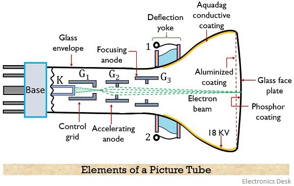
There are two major elements of a monochrome picture tube that are electron gun and a fluorescent screen.
1. Electron gun
This section is composed of a cathode and some grids.
- Cathode: The cathode of the tube comprises of a nickel cylinder whose ends are coated with either thoriated tungsten or barium and strontium oxides. The major reason for specifically using these materials at the coating is that they possess low work-function thus releases a sufficient number of electrons when heated.
A heater wire is present close to the cathode, that provides sufficient heat to the cathode. An external ac voltage is used for indirect heating of the cathode. - Control Grid G1: The control grid G1 is a cylindrical structure with a small opening that allows the confinement of released beam inside the tube. Grid G1 is provided somewhat negative potential wrt the cathode.
- Accelerating Grid G2: It is a cylindrical structure of nickel and is also known as the screen grid. The internal baffles provide a restricted path to the electron beam.
A positive potential of around 400 V is provided to accelerating grid/anode thus it allows the acceleration to the beam emitted from the cathode. - Focusing Grid G3: This grid in the tube structure provides a sufficient electric field to the moving electrons in order to prevent spreading inside the tube. A high positive potential of about 500 V is given to focusing anode so that a highly focused beam when strikes the fluorescent screen produce sharp spot on it.
The inner surface of the tube is coated with Aquadag which is provided with an extremely high voltage of around 18KV. This high potential Aquadag coating prevents spreading of the electron beam released from the focusing anode. - Deflection Yoke: The moving electron beam experiences magnetic deflection by the deflection yoke present outside the tube.
2. Fluorescent Screen
The screen where the electron beam is allowed to incident is basically a high-quality glass faceplate. The thickness of the glass sheet is 1.5 cm.
Phosphor is coated in the inner region of the material. The electron beam when strikes the phosphor coating then the phosphor particles glow thereby giving rise to the image on the screen. Also to prevent losses, a thin coating of aluminium is present towards the gun side of the phosphor screen.
Working of Monochrome Picture Tube
In order to understand the working firstly, we have to consider the structure of the monochrome picture tube shown above.
Due to indirect heating of the cathode, an electron beam is emitted from the surface of the cathode. As we have already discussed that G1 is at lower potential wrt cathode. Thus electrons propagate towards the control grid.
Further, the beam from a small aperture of the control grid is made to travel inside the tube.
- As we can clearly see in the figure shown above that an accelerating grid G2 is present. The presence of this grid provides sufficient acceleration to the electron moving inside the tube.
- The tube consists of a focusing grid with a comparatively larger diameter than accelerating anode. Also, a very high positive potential is provided at the focusing anode that allows the propagation of a focused beam of electron inside the tube.
It is to be noted here that for the production of an image on the screen, the electron beam must strike the phosphor surface with sufficient velocity.
Therefore, the aquadag layer is coated on the inner region of the tube, that acts as the second anode for the tube and it provides sufficient velocity to the moving electrons.
- Basically, a very high potential is provided to this region and so electrons accelerated by this high potential gains very high velocity before striking the screen.
As during motion, the electrons gain kinetic energy, so when these electrons strike the phosphor screen, then they transfer their energy to the atoms in the phosphor screen.
This energy is gained by the electrons in the valence shell of the atom in order to reach the conduction band. On returning back to the lower energy state, the electrons emit the gained energy in the form of electromagnetic radiation.
And as its frequency range lies in the spectral region thus is seen by the eyes of the viewer. However, the intensity of the light produced on the screen will depend on the strength of the electron beam striking the surface.
- It is to be noted here that sufficient modulation to the electron beam is provided by the video signal that resultantly produces brightness variations in the screen. So, as a function of time, bit-by-bit picture gets created on the screen.
As we know that that a high-velocity beam when strikes the fluorescent surface then along with producing light energy, secondary emission of electrons will also take place.
So, these secondary electrons must be collected somewhere. Because the presence of these secondary electrons near the phosphor screen will create a negative space charge and this will prevent the primary beam from reaching the screen.
Therefore, to avoid this the secondary emitted electrons are made to be collected at the conductive coating having very high positive potential. So, this conductive (aquadag) coating along with increasing the velocity of moving electrons also eliminates unnecessary secondary electrons from the tube.