Definition: A Vidicon is a type of camera tube whose basis of working is photoconductivity. Basically it changes optical energy into electrical energy by the variation in resistance of the material with respect to the illumination.
These camera tubes were invented in the 50s. The tube length is around 12 to 20 cm with a diameter of 1.5 to 4 cm. Due to small size and easily operational characteristic, at the time of development, they became highly popular.
Around 5000 to 20, 000 hours is generally considered as the estimated life span of Vidicon.
Content: Vidicon Camera Tube
Principle of Operation of Vidicon
Photoconductivity is the basis of working of a Vidicon. We all know that photo means light and so photoconductivity is the property that shows the variation in conductivity of any material with the change in intensity of light falling on that surface.
More simply we can say it as the application of optical energy changes the electrical conductivity of the material. And as we have already discussed that a camera tube changes optical energy into an electrical one.
Thus this principle is applied in Vidicon in order to convert light energy into electrical energy.
With the advancement in technology, even more, compact camera tubes were developed that includes the designing variation in the electron gun.
Hence this has given rise to various derivatives of Vidicon that are Plumbicon, Saticon, Newvicon etc.
Construction of Vidicon
The figure below represents the cross-sectional representation of a Vidicon camera tube:
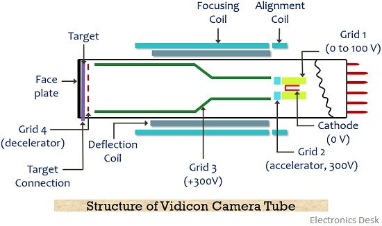
The electron beam is used for scanning the target plate. This electron beam is produced by an electron gun. This is focussed towards the photoconductive layer using focusing coils. By the presence of deflection coils, the electron beam scans the target horizontally as well as vertically.
The gun is usually composed of a cathode that emits electron beam.
- Grid 1: It is abbreviated as G1 and is known as the control grid.
- Grid 2: G2 is known as accelerating anode, provided with a voltage of around 300 V.
- Grid 3: G3 acts as the accelerating grid that further accelerates the electron beam emitted by a combination of cathode and G1 and initially accelerated by the accelerating anode. This highly accelerated beam is focussed towards the target plate by the electrostatic field of the grid and the magnetic field offered by the focusing coil.
- Grid 4: A wire mesh denoted as G4 acts as a deaccelerating anode that allows the landing of an electron beam with low velocity over the target plate in order to prevent secondary emission.
The photoconductive material over here is generally an intrinsic semiconductor that offers high resistance in darkness and low resistance when exposed to light.
The target region is composed of a faceplate that has a layer of tin oxide deposited over it. This layer is known as a signal electrode and creates electrical contact with a metal target electrode.
This electrode consists of a photoconductive layer of selenium or antimony trisulphide towards the side of the electron gun. This conductive coating is also known as the target electrode. The signal plate is provided with positive external dc supply.
Working of Vidicon Camera Tube
Initially, light from a scene is allowed to fall on the faceplate by passing it through a lens system. As we have already discussed that the target plate is composed of 2 layers, one is of tin oxide while at the other side a photoconductive layer is present.
So when light reaches the photoconductive material (target) as shown in the figure above, then by absorbing the light energy, free electrons get generated. Due to the externally supplied positive potential at the signal plate, the electrons start to migrate towards it and this causes vacancy of electrons on the photoconductive region.
Thereby generating positive charges over the surface of the material. It is to be noted here that the created positive charge will be proportional to the number of free electrons produced by the photon energy.
So we can say that the charge-image generated on the layer towards the gun side is proportional to the incidenting optical image.
As we have already discussed that the photoconductive layer offers high resistivity nearly about 20 MΩ in the dark while low resistivity nearly about 2 MΩ in bright light. Thereby causing the generation of charge on its surface according to the intensity of falling radiation.
Further, a scanning beam is emitted by the cathode that is accelerated by the accelerating grid and is focussed towards the photoconductive layer. Just before landing on the surface of the material, the beam suffers deceleration. This deceleration is performed so that the falling electrons may not cause secondary emission.
So a low-velocity scanning electron beam reaches the target plate. Thus the electrons from the beam start depositing on the surface of the material in order to neutralize the vacancy of electron created in it.
This resultantly produces an electric current.
It is to be noteworthy here that only the sufficient amount of electrons that are needed to neutralize the positive charge will be utilized. However, the remaining electrons that were not collected at the plate will travel a reverse path due to the presence of positive grids.
The figure below represents the electric circuit of Vidicon: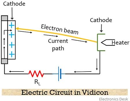
Thus we can say that the scanning current is proportional to the deposited electrons and so to the brightness of the incident light. This causes the video signal as the output across the load resistor.
The scanning of every single element of the target is performed at a regular interval of around 40 ms. Thus is a stored action.
This charge on the plate remains the same till the time each pixel gets neutralized. Thereby enhancing the sensitivity of the tube.
What is Image Lag?
Image lag is basically the term defined as the time delay in generating the signal current according to the frequent variations at the time of illuminating the target.
In the case of photoconductive camera tubes, this delay can occur due to two reasons thus defined differently. The two different image lag is as follows:
- Photoconductive Lag: This type of image lag occurs when the photoconductive material somewhat responds slowly to the brightness variation. Basically in this case when light incident on the target plate then few numbers of electrons fails to migrate to the signal plate.
This causes the existence of a faded charge image of the scene for some seconds. And this faded image is displayed on the screen even after the removal of the actual scene. - Capacitive Lag: When scanning beam is provided to the target plate then the time needed for recharging of the plate depends on the pixel capacitance and the resistance of the beam-time constant CtRb.
The value of the time constant must not be very high, as this will lead to incomplete charging of the plate in one scan. And so this will cause the generation of the smeared tail (or blurred end) behind the moving objects.
So to prevent this high beam current must be provided that resultantly cause a reduction in beam resistance thereby charging the discharged pixels in a single scan.
Advantages
- Small-sized and light-weighted.
- It provides good resolution.
- Vidicon offers variable sensitivity towards illumination, by causing variation in target voltage.
- It provides better SNR than image orthicon TV camera tubes.
Disadvantages
- Though it provides good sensitivity, somewhat less than the sensitivity of image orthicon.
- It offers around 20 nano ampere of dark current.
- The problem of image lag may lead to burn-in of the image at the target when exposed to long-duration in bright scenes.
Applications
Initially, Vidicon camera tubes were used in a domestic or industrial recording like in CCTVs. But with the arrival of improved tubes, these are finding major uses in the television industry, in education, and aerospace applications.
Is the vidicon tube still in use in television system?