Plumbicon camera tube is a photoconductive type of camera tube as photoconduction is the basis of its operation. This camera tube was invented in the year 1963 by Philips.
One of the major reasons behind the invention of Plumbicon is the drawback of image lag associated with Vidicon tubes.
To eliminate this drawback, the target of Plumbicon is fabricated in the form of a PIN diode. In this article, we will discuss the detailed operating principle of Plumbicon.
It is called so due to the presence of lead (Pb or Plumbum) as the photoconductive material in the target plate of the tube.
Content: Plumbicon
Construction of Plumbicon
The figure below shows the structure of the Plumbicon camera tube:
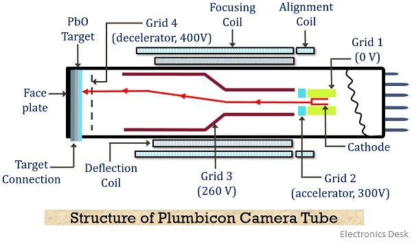
The tube consists of a faceplate whose inner region is coated with a layer of tin-oxide that forms a strong n-type surface. It shows transparency towards the light that is allowed to fall on its surface and holds conductive property. It acts as a signal plate of the target.
Over this layer, a photoconductive layer of lead monoxide (PbO) is deposited that acts as intrinsic region. And in order to form the P region, pure PbO is doped with a p-type material so as to form a complete PIN diode structure that acts as a target.
- The target plate is usually 15 mm wide and scanning beam strikes the p region of the target.
The structure holds an electron gun section that basically comprises of a cathode that emits the electrons, a control grid G1 and an accelerating grid G2.
The beam emerging from the cathode of the gun scans the target plate.
The electrostatic and magnetic focusing is provided to the travelling electron beam by the use of grid 3 and external focusing coil. Here electrostatic focusing is given by G3 while external focusing coils gives the desired magnetic focusing.
- Magnetic focusing is employed in order to provide sufficient convergence to the moving electrons at the centre so as to have sharp spots on the surface of the target.
A wire-mesh screen is present near the target that functions as a sort of covering for the electron gun. It is the grid 4 of the tube structure.
The voltage given to:
- Signal plate is 50 V
- Control grid, G1 is 0 V
- Accelerating grid, G2 is 300 V
- Focusing grid, G3 is 260 V
- Wire mesh, G4 is 400 V
As it is clear that G3 is at lower potential wrt G2, therefore, this leads to a reduction in the velocity of electron reaching the target.
The potential at the target is 40 V this is done in an urge to have much negative potential at the target wrt wire-mesh screen.
This is done to provide desired deceleration to the moving electrons. As by this, they approach the target with almost zero velocity in a tangential manner thereby avoiding the chances of secondary emission.
Working of Plumbicon
Photoconductivity forms the basis of operation of Plumbicon. This means that the action of light falling from a scene on the target varies the conductivity of the material. We know that camera tubes convert optical energy into electrical energy.
Vidicon is also used for the same but a major drawback of image lag is associated with it. Therefore, Plumbicon was invented.
As we have already discussed that the target plate of Plumbicon operates as a PIN diode. So let us now understand how a Plumbicon operates by considering the figure shown above.
When light is allowed to fall on the surface of the target then electrons are emitted from the n region of the PIN target structure.
The intrinsic layer provides a high electric field gradient this leads to sweeping of released electrons from the target plate rapidly. Thereby preventing the chances of image lag present in case of Vidicon.
The PIN structure of the target acts as a capacitor as shown below: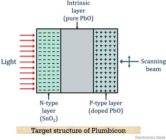
Due to the photoconductive nature of the target (capacitor), in the absence of light, the material offers high resistance. And so the applied bias voltage appears across the capacitor.
- When the capacitor is exposed to radiation, then the resistance existing across it reduces to an extremely low value. This allows the leakage of charge through the capacitor. (Or we can say the emission of electrons from the surface of the target.)
- However, if the capacitor is exposed with an image of dark regions (or low optical energy), then high value is resistance is offered by it, leading to leakage of extremely low or negligible charge from the capacitor.
So, we can say that when the bright image falls on the target (capacitor) then it reduces the resistance, thereby causing emission of charge and this leads to increase in voltage existing on one side of the capacitor.
While in case of incidence of the dark image, the resistance offered will be higher leading to low voltage.
This voltage towards the gun side is nothing but the charge image formed in proportion with the applied optical image.
More simply, we can say, the charge image produced on the gun side of the target is the accumulation of positive charge on it.
Further, a scanning beam is allowed to an incident on the surface of the target. The beam is emitted from the cathode and potential at G2 provides required acceleration to the moving electrons. Also electrostatic and magnet focusing is provided to the beam by G3 and the focusing coil.
- In order to prevent the secondary emission of electrons from the surface of the target, G4 provides desired deceleration to the moving electrons.
This causes the striking of electrons to the target with almost zero velocity. Thus the positive charge at the plate gets neutralized without causing secondary emission.
The neutralization of positive charge on the surface of the target results in the flow of current. The amount of current is dependent on the voltage present on the gun side of the plate thereby showing proportionality with the intensity of incident light.
This resultantly produces video signal at load.
Advantages
- It offers more sensitivity than Vidicon.
- Plumbicon eliminates the problem of image lag.
- It possesses high SNR of about 47 dB.
- The value of dark current is almost negligible i.e., 1 nA.
- It is small in size than the image orthicon.
Disadvantages
- It is less sensitive than image orthicon.
- Plumbicon has a large size than Vidicon tube and thus bulkier that the latter.
- It offers less resolution than a Vidicon tube.
Applications
As the problem of image lag is eliminated in Plumbicon thus is highly suited for colour TV applications. These camera tubes are also used in studious and outdoor shooting.