A travelling wave tube is a high power amplifier used for the amplification of microwave signals up to a wide range. It is a special type of vacuum tube that offers an operating frequency ranging between 300 MHz to 50 GHz.
Travelling wave tubes are non-resonant structures that offer continuous interaction of applied RF field with the electron beam over the entire length of the tube. Due to this reason, it provides wider operating bandwidth.
Content: Travelling Wave Tube
Basic Concept
Travelling wave tubes are abbreviated as TWT. It is majorly used in the amplification of RF signals. Basically a travelling wave tube is nothing but an elongated vacuum tube that allows the movement of electron beam inside it by the action of applied RF input.
The movement of an electron inside the tube permits the amplification of applied RF input. As it offers amplification to a wide range of frequency thus is considered more advantageous for microwave applications than other tubes.
It offers average power gain of around 60 dB. The output power lies in the range of few watts to several megawatts.
A travelling wave tube is basically of two types one is helix type and the other is coupled cavity. Here in this section, we will discuss the detailed construction and working of a helical travelling wave tube.
Construction of Travelling Wave Tube
The figure here shows the constructional structure of a TWT:
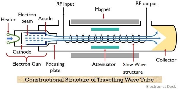
As we can see that the helical travelling wave tube consists of an electron gun and a slow-wave structure. The electron gun produces a narrow beam of the electron. A focusing plate is used that focuses the electron beam inside the tube.
A positive potential is provided to the coil (helix) with respect to the cathode terminal. While the collector is more positive than the coil (helix). In order to restrict beam spreading inside the tube. A dc magnetic field is applied between the travelling path by the help of magnets.
The signal which is needed to be amplified is provided at one of the ends of the helix, present adjacent to the electron gun. While the amplified signal is achieved at the opposite end of the helix.
In the figure, we can clearly see that attenuator is present along both the sides of the travelling wave tube. This is so because travelling wave amplifiers are high gain devices, so in case of poor load matching conditions, oscillations get build up inside the tube due to reflection.
Thus in order to restrict the generation of oscillations inside the tube attenuators are used.
Attenuators are basically formed by providing a metallic coating over the surface of the glass tube. Aquadag or Kanthal are majorly used for this.
It is to be noteworthy that a slow-wave structure is considered here, the reason is to maintain continuous interaction between the travelling wave and electron beam.
Need of Slow-Wave Structure
We know that the velocity of the electromagnetic wave is very much higher when compared with the phase velocity of the electron beam emitted by the electron gun.
Basically the RF wave applied at the input of TWT propagates with the speed of light (i.e., 3 * 108 m/s). While the propagating velocity of the electron beam inside the tube is comparatively smaller than the velocity of RF wave.
If we try to somehow accelerate the velocity of the electron beam, then it can be accelerated only to a fraction of velocity of light. So it is better to reduce the velocity of the applied RF input in order to match the velocity of the electron beam.
Therefore, a slow-wave structure is used that causes a reduction in the phase velocity of the RF wave inside the TWT.
The slow-wave structures can be of different types like a single helix, double helix, zigzag line, corrugated, coupled-cavity or ring bar type etc.
A single helix slow-wave structure is formed by wounding a wire of element like tungsten and molybdenum in the form of a coil. The helical shape of the structure slows the velocity of the wave travelling along its axis to a fraction of about one-tenth of c.
This is so because due to the helical shape of the structure, the wave travels a much larger distance than the distance travelled by the beam inside the tube. So, in this way, the speed of wave propagation depends on the number of turns or diameter of the turns.
More specifically we can say that change in pitch can vary the speed of wave propagation inside the tube.
The equation given below shows the relation of phase velocity of the wave with the pitch of the helix:
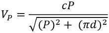
: c = velocity of light (3 * 108 m/s)
VP = phase velocity in m/s
P = pitch of helix in m
d = diameter of the helix in m
Therefore, this causes continuous interaction between the RF input wave and the electron beam as the velocity of propagation of the two is not highly different. As such interaction is the basis of working of TWT thus slow-wave structures are used.
Working of Travelling Wave Tube
Till now we have discussed the complete constructional structure of TWT. Let us now understand how the signal gets amplified while travelling inside the tube.
The applied RF signal produces an electric field inside the tube. Due to the applied positive half, the moving electron beam experiences accelerative force. However, the negative half of the input applies a de-accelerative force on the moving electrons.
This is said to be velocity modulation because the electrons of the beam are experiencing different velocity inside the tube.
However, the slowly travelling wave inside the tube exhibits continuous interaction with the electron beam.
Due to the continuous interaction, the electrons moving with high velocity transfer their energy to the wave inside the tube and thus slow down. So with the rise in the amplitude of the wave, the velocity of electrons reduces and this causes bunching of electrons inside the tube.
The growing amplitude of the wave resultantly causes more bunching of electrons while reaching the end from the beginning. Thereby causing further amplification of the RF wave inside the tube.
More specifically we can say that forward progression of the field along the axis of the tube gives rise to amplification of the RF wave. Thus at the end of the tube an amplified signal is achieved.
The positive potential provided at the other end causes collection of electron bunch at the collector.
The magnetic field inside the tube restricts the spreading of the beam as the electrons possess repulsive nature.
However, as the TWT is a bidirectional device. Therefore, the reflected signal causes oscillations inside the tube. But as we have already discussed earlier that the presence of attenuators reduces the generation of oscillations due to reflected backwave.
Sometimes despite using attenuators, internal impedance terminals are used that puts less lossy effects on the forward signal.
Applications of TWT
- Travelling wave tubes are highly used in continuous wave radar systems.
- These amplifying tubes also find application in broadband receivers for RF amplification.
- TWT’s are also used to get high power output in satellite transponders.
So from the above discussion, we can conclude that no resonant structure is present in the interaction space. Thus provides amplification up to a wide bandwidth operating range.
However, the input and output coupling arrangements must be considered carefully as they limit the operating range.