Definition: An antenna that is formed by etching out a patch of conductive material on a dielectric surface is known as a patch antenna. The dielectric material is mounted on a ground plane, where the ground plane supports the whole structure. Also, the excitation to the antenna is provided using feed lines connected through the patch.
As it is formed using a microstrip technique by fabricating on a printed circuit board thus is also known as Microstrip antenna or printed antenna.
Generally, patch antennas are considered as low profile antennas and are used for microwave frequency applications having frequency greater than 100 MHz.
Content: Patch Antenna
- Construction
- Working
- Radiation Pattern
- Characteristics
- Feeding Methods
- Advantages
- Disadvantages
- Applications
Construction
Patch antenna has 2D geometry. These antennas come in various shapes where its shape is defined by the shape of the metallic patch placed on the dielectric material.
The patches can be rectangular, square, circular, triangular, annular or elliptical in shape.
Suppose we have a rectangular patch antenna, which is formed by fabricating a rectangular metallic patch on a dielectric coated ground plane. This can be said in simple terms that a dielectric material having a conducting patch is supported by a ground plane.
The figure here represents the top view of the microstrip antenna: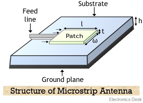
Here we have shown the simplest form of patch antenna where the patch etched on the substrate is half-wavelength long while the thickness of the same is extremely less than λ. Also, excitation to the antenna is provided through feed lines connected to the patch.
Here the substrate which is nothing but the dielectric material is used to separate the strip from the ground plane.
Basically the patch or strip and the feed lines are photo-etched on the surface of the substrate. As we have already discussed that patches can be formed in multiple shapes, however, due to easy fabrication rectangular, circular or square-shaped patches are generally used.
Till now we have discussed a single patch etched on a substrate. But patch antennas can also be formed with a collection of multiple patches on a dielectric substrate. Either single or multiple feed lines are used to provide excitation to the antenna.
The presence of arrays of microstrip elements provides greater directivity, higher gain, increased transmission range with less interference.
Working of Patch Antenna
A microstrip or patch antenna operates in a way that when current though a feed line reaches the strip of the antenna, then electromagnetic waves are generated.
The waves from the patch start getting radiated from the width side. But as the thickness of the strip is extremely small thus the waves that are produced within the substrate get reflected by the edge of the strip. The continuous structure of the strip along the length does not permit the emission of radiation.
Furthermore, on experiencing a sudden discontinuity in the structure of the patch, radiations are again emitted from the second width side of the patch.
As this discontinuous structure favors reflections, thus the patch antenna radiates only a small fraction of supplied incident energy.
This makes the antenna inefficient, that rather displaying the characteristics of a good radiator, it somewhat acts as a cavity.
The low radiating ability of microstrip antenna allows it to cover the only small distances of wave transmissions like local offices, stores or any indoor locations. As such inefficient transmission is not supportable at a centralized location in an extremely large area.
Generally, hemispherical coverage is provided by a patch antenna at an angle of 30⁰ to 180⁰ at width from the mount.
Radiation Pattern
The figure below represents the radiation pattern of the microstrip antenna: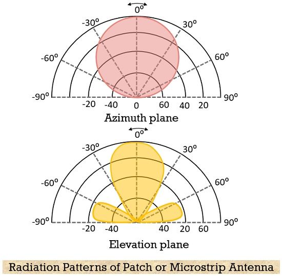
Characteristics
- The patch of the antenna must be a very thin conductive region, t<<λ0 (: λ0 free space wavelength).
- The ground plane must have comparatively very large dimensions than the patch.
- Photo-etching is done to fabricate the radiating element and feed lines on the substrate.
- A thick dielectric substrate with dielectric constant within the range of 2.2 to 12 provides good antenna performance.
- Arrays of microstrip elements in the antenna configuration provide greater directivity.
- Microstrip antennas provide high beamwidth.
- A very high-quality factor is offered by a patch antenna. A large Q results in a narrow bandwidth and low efficiency. However, this can be compensated by increasing the thickness of the substrate. However, the increase in thickness beyond a certain limit will cause an unwanted loss of power.
Feeding Methods of Patch Antenna
There are various methods through which the microstrip antenna is fed.
However, the classification of feeding methods is done in two ways:
- Contacting feed: In this method, the power is directly given to the radiating element. This is done using a microstrip or coaxial line.
Thus there are two types of contacting feed:
- Microstrip feed: It is a conducting strip having width extremely smaller than the width of the radiating element. Due to thinner dimensions of the strip, the feed line offers easy etching on the substrate. The feed line to the structure can be provided either at the center, inset or offset.
- Coaxial feed: It is one of the commonly used methods for feeding the antenna. Coaxial feeding is provided to the antenna in such a way that the inner conductor is connected to the patch. While the outer conductor is attached to the ground plane.
With the variation in the position of the coaxial feed, the impedance also varies. As the feed line can be connected anywhere within the patch thus facilitates impedance matching.
However, connecting the feed line with the ground plane is a bit difficult as this will require drilling a hole in the substrate.
- Non-contacting feed: The power from the feed line is provided to the radiating element using electromagnetic coupling. The two types of non-contacting feed are:
- Aperture: It is a type of electromagnetic coupling, that permits providing excitation to the radiating element without forming direct contact with it.
In this method, two dielectric substrates are considered which are separated by a ground plane. The feed line is provided through the ground plane. The patch is present at the upper dielectric substrate.
As the feed does not form direct contact with the radiating patch. Thus a slot is formed on the conducting plane, that allows the coupling of the energy of the feed line to the antenna.
The ground plane isolates the feedline from the radiating element. The length of the slot and the width of the feedline permits controlling.
It is the most difficult method to feed the antenna. This is so because the two dielectric substrates cause difficulty in fabricating the microstrip in the structure. - Proximity: It is also known as indirect feed in which the ground plane is absent. A slot is present on the conductive surface of the antenna and coupling is provided using a microstrip line. It is easy to manufacture in comparison to an aperture coupled feed antenna.
It offers low spurious radiation and the largest bandwidth.
Advantages
- The antenna is of small size and less bulky.
- It offers an easy fabrication process.
- Due to less volume and small size, there is an easy installation.
- It provides easy integration with other devices.
- It can perform dual and triple frequency operations.
- The arrays of the antenna can be easily constructed.
- It offers a high degree of robustness over rigid surfaces.
Disadvantages
- The antenna efficiency is low.
- These antennas show highly sensitive behavior towards environmental factors.
- These exhibit low power handling ability, low gain, and narrow bandwidth.
- These are more prone to spurious feed radiation.
- There are more dielectric and conductor losses in microstrip antennas.
Applications of Patch Antenna
- The low profile structure of microstrip antennas offers its wide use in wireless communications. This is the reason these antennas show compatibility towards handheld devices like pagers and mobile phones.
- Due to the thin structure of these antennas, these are used as communication antennas on missiles.
- Satellite communication and microwave applications also make use of microstrip antenna due to its small size.
- GPS i.e., the Global Positioning System is one of the major advantages of microstrip antennas. As it offers ease in tracking vehicles and marines.
- These antennas also find applications in phased array radars that can handle bandwidth tolerance up to some percentage.
This is all about patch or microstrip antennas.