Yagi-Uda Antenna is an antenna that is well known for its high gain and directivity. A Yagi-Uda antenna is formed by a combination of 3 major elements i.e., driven element, reflector and directors.
These are basically designed to operate in very high and ultra-high frequency bands and offers the operating frequency ranging between 30 MHz to 3 GHz.
Content: Yagi-Uda Antenna
- History
- Construction
- Working
- Characteristics
- Radiation Pattern
- Advantages
- Disadvantages
- Applications
History
Yagi-Uda antenna was named after two scientists from Japan, who developed and explained this antenna.
Professor Shintaro Uda initially explained the theory of this antenna in the Japanese language in the year 1928. However, later this antenna was explained in English by Hidetsugu Yagi.
The English explanation of Yagi-Uda antenna made the theory worldwide famous. But as the antenna was initially proposed by S. Uda so on behalf of contributions made by both of them, the antenna is given an appropriate name thus known as Yagi-Uda Antenna. It is sometimes known as Aerial or Yagi Antenna.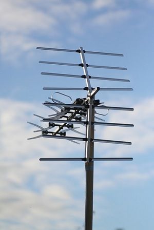
Though this was developed in the year 1928 but is adopted for personal and commercial use since 1930.
Construction
A Yagi-Uda antenna has 3 main elements that combinedly form its structure. These 3 major elements are driven element which is generally a half-wave folded dipole, a reflector and directors.
The structure contains one driven element and a reflector while directors can be more than one.
The figure below represents the structure of the Yagi-Uda antenna:
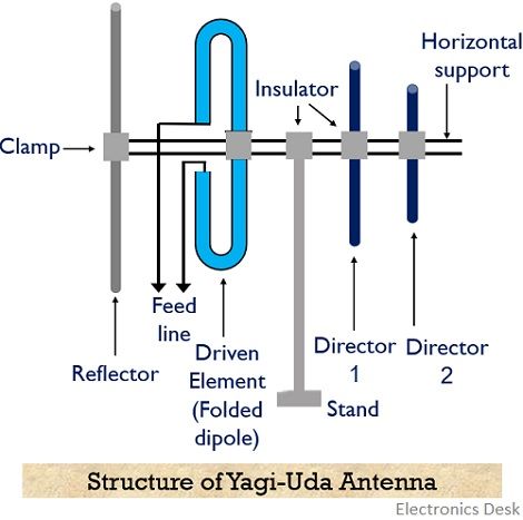
Basically, the arrangement is said to be an array of active and parasitic elements. The dipole generally a metallic rod acts as the active element as external feeding is provided to it using transmission lines. While reflector and directors are the parasitic elements of the structure.
The parasitic elements are also metallic rods placed parallelly in the line of sight orientation with respect to the driven element.
It is noteworthy here that no external excitation is provided to the parasitic elements. However, when the dipole is excited using a transmission line then the current that flows through the driven element induces voltages in the parasitic elements.
All these elements are mounted on a centre rod, that acts as horizontal support.
The reflector is present at one of the ends of the metallic rod and has length around, 5% greater than the length of the driven element. While the directors are almost 5% shorter than the driven element (i.e., λ/2 at the resonant frequency) and are placed at the other side of the dipole as these are used to provide maximum directivity to the antenna.
So, for 3 element aerial, the lengths of the elements can be considered as: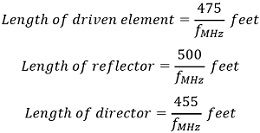
Working of Yagi-Uda Antenna
We know that external excitation is directly provided to the active element of the arrangement i.e., the dipole. The flow of current through the active element induces a voltage in the parasitic elements that cause current to flow through it.
The element having a length greater than λ/2 i.e., the reflector, shows inductive characteristic, therefore, the current in the reflector lags the induced voltage. Whereas, the one shorter than the half-wave dipole i.e., the director is capacitive. So, the current flowing through it leads the voltage.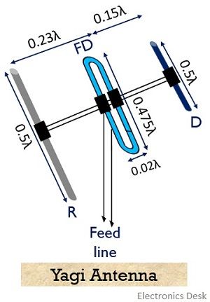
As we know that director is placed in front of the driven elements, so, these directors add the field of the driven element in the direction away from it. When multiple directors are placed in the arrangement then each director will provide excitation to the next one.
Also, the reflector in the opposite direction as that of the director when accurately placed adds the field in the direction towards the driven element. This is done in order to reduce the losses due to the back radiated wave as much as possible.
In order to get the additional gain, multiple directors can be used in the direction of the beam.
The spacing between the elements to form a Yagi -Uda structure is as follows:
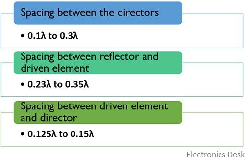
Basically, the induced voltage and the current flowing due to the induced voltage in the element varies with the spacing between the active and parasitic elements along with the reactance associated with the elements.
It is to be noted here that with the increase in distance between driven element and director, there will be more need for capacitive reactance in order to provide accurate phasing to the current in the director. Thus, the length of the director is kept small to get the capacity reactance.
So, we can compile all the above-discussed factors as:
Initially, excitation to the driven element is provided using feed lines. This causes the emission of radiation from reflector towards the director. Moreover, a portion of the emitted radiation excites the parasitic elements, that further re-radiate the radiations.
The length of the elements and spacing is of great importance here because radiated energy from each element gets summed in the front direction and so cancels the back radiated wave.
Characteristics
- A Yagi-Uda antenna is said to be beam antenna if it is only 3 elements array i.e., a driven and reflector and only a single director.
- It offers moderate unidirectional directivity.
- The gain offered by the Yagi-Uda antenna is around 8 dB with front to back ratio of approximately 20 dB.
- In order to increase the directivity, more elements can be added in the array.
- Another name to this antenna is super directive antenna due to its high directive gain.
- It is frequency sensitive thus is a fixed frequency device.
Radiation Pattern of Yagi-Uda Antenna
Let us now see the radiation pattern of the Yagi-Uda antenna, which is given below: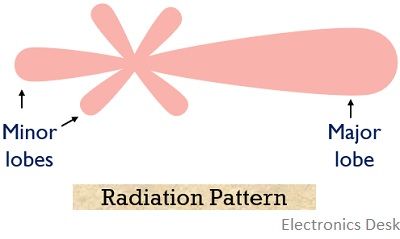
Here the major lobe represents the forward radiated wave while the major lobe represents the back radiated wave.
Advantages
- Yagi-Uda antenna offers very high gain.
- It possesses a highly directional characteristic because of the use of directors.
- It is a low-cost antenna.
- Yagi-Uda antenna shows suitability towards high-frequency operations.
- It is light in weight and feeding mechanism is also simple.
- It is power efficient.
- Along with all the above-defined advantages, it also offers ease of construction and handling.
Disadvantages
- These antennas are highly affected by atmospheric conditions.
- Noise is the major factor that disturbs the overall performance of the antenna.
Applications of Yagi-Uda Antenna
These antennas are widely used in the field of TV signal reception, as it has excellent receiving ability. Even astronomical and defence related applications make use of Yagi-Uda Antenna. Also, radio astronomy utilizes these antennas.
Thanks for such useful information. Very informative.