Radiation Pattern of Antenna shows the distribution of energy radiated by the antenna in space. More simply, the radiation pattern is a trace out that corresponds to the radiation properties of the antenna in space coordinates (i.e., with respect to angle and distance).
It is a graphical way of showcasing the radiation from the antenna as a function of direction and also known as Field Strength Pattern.
The measurement of the antenna pattern is generally done at a quite large distance where the power distribution is independent of the distance. This is so because the signal emitted from the antenna is desired to be propagated to large distances thus the distribution of the radiated power in space must be considered at an electrically large distance for pattern measurement.
Content: Radiation Pattern
Introduction
We know that the sole purpose of the antenna is to transmit and receive electromagnetic waves so, the energy radiated from an end is received at the other end.
However, whenever we talk about the radiated energy from the antenna then practical analysis suggests that the strength of the energy radiated by the antenna is not the same in all the directions.
This signifies that there is no uniformity in terms of the strength of the radiated energy. Basically, the non-uniformity of the field strength is such that it is more in one direction and comparatively less or zero in other directions.
Antenna pattern is regarded as the fundamental requirement of the antenna as it is directly associated with how the radiated energy is distributed in space.
Antenna Pattern
As we have discussed in the previous section that the distribution of energy radiated by the antenna is non-uniform. Also, the energy which the antenna radiates in a specific direction is measured relative to field strength at a point considered at a particular distance from the antenna.
Now the question arises – how the field strength is calculated?
So, this is a rational value where the numerator corresponds to the voltage at two specific points on the electric lines of force and denominator is the distance of separation between the two points. The measuring unit of the antenna pattern is generally volt/meter.
As it is a fundamental characteristic of antenna thus, is needed to be necessarily measured and with the knowledge of the frequency of operation, the energy distribution in space (i.e., the radiation pattern) can be determined.
In simplest terms, the radiation pattern of the antenna is a graphical representation that shows how the actual field strength of the electromagnetic field is changing at different points which are at equal distances from the antenna. Thus, is of three-dimensional nature hence cannot be totally represented on a sheet of paper.
While sketching the radiation pattern, the point where the antenna is present is taken as the centre point and an imaginary spherical region of the fixed radius is considered around it. Now, at every point that lies within the spherical region, the electrical field strength is measured and a three-dimensional figure is drawn according to the reading of the measurement.
This resultantly provides the field strength within the spherical region at a specific distance in the desired direction.
The figure below represents a 3D field pattern of directional antenna, where r represents the pattern radius which is proportional to the field intensity as a function of two spherical coordinates θ and φ.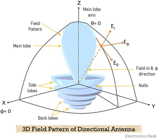
As we have already discussed that the spherical coordinate (r, θ, φ) system is used to specify the field strength within the spherical surface. However, the radiation pattern is independent of the radius of the sphere where r >> λ.
A three-dimensional radiation pattern ensures the radiation for all angles of θ and φ.
As we know that a 3D figure cannot be drawn on a plain sheet of paper thus to draw the solid figure in a plane sheet a fixed point is considered (say the centre of the sphere) and it is cut by that particular plane.
The cross-sections are formed generally in the horizontal plane (i.e., θ = 90°) and in the vertical plane (i.e., φ = constant) and are known as a horizontal pattern and vertical pattern respectively. And the obtained figure now represents the radiation pattern in the usual manner.
It is to be noted here that radiation pattern is different for various antennas also the position of the antenna with respect to the ground puts an effect on the same.
The antenna radiation when defined in terms of field strength is known as Field Strength Pattern and when defined in power per unit solid angle called Power Pattern. But both of these are interrelated to one another as the power pattern is proportional to the square of the field strength pattern.
Principal Patterns
As we have discussed recently that antenna pattern is a crucial parameter of antenna structure and its performance is defined according to its principal E-plane and H-plane patterns.
When a linearly polarized antenna is considered then the plane of electric field vector where there is maximum radiation is known as E-plane pattern. As against, the plane of the magnetic field vector as the direction of maximum radiation is called the H-plane pattern.
Mostly the antennas are oriented in a way that out of the two, at least one of the principal plane patterns must overlap with the geometric principle planes.
The figure shown below represents the above-discussed criteria.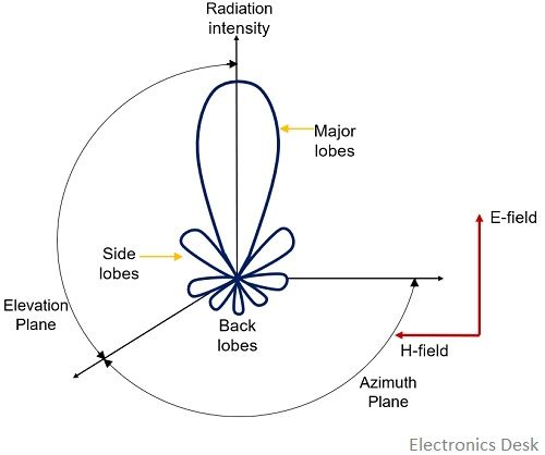
Here, E-plane is represented by the x-z plane while H-plane is shown by the x-y plane.
Radiation Pattern Lobes
As the radiation pattern corresponds to the field distribution in space thus it has various parts known as lobes. These are classified as main lobe and side lobe. The main lobe is also called as major lobe while the side lobe includes minor lobe and back lobe.
The figure here shows a symmetrical polar pattern with the radiation lobes: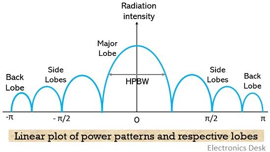
These are classified according to the amount of their radiation intensity. The major lobes have more radiation intensity than the side lobes.
1. The major lobe corresponds to the direction of maximum radiation of the antenna.
2. All the lobes which are present except the major lobe are known as the minor lobe. These are of two types:
- A side lobe is a minor lobe present adjacent to the main lobe.
- A back lobe is another minor lobe present on the opposite side of the main lobe.
Minor lobes are the radiation of the antenna in an undesired direction and should be reduced to an extent as much as possible.