Antenna measurement is regarded as a crucial aspect of antenna designing. This is so because while designing the antenna, antenna measurement is performed at different levels that lead to help in checking whether the desired specifications have met or not.
It involves a method where the source antenna (either transmitting or receiving) is placed at various positions in correspondence to the Antenna Under Test (AUT). And the various antenna parameters are determined for each individual location.
Content: Antenna Measurements – Impedance Measurement
Introduction
We all know that the major parameters that decide the performance of the antenna system at the time of signal transmission and reception are gain, efficiency, radiation pattern, impedance along with beam width, bandwidth, power handling capability, etc.
So, by the use of proper equipment, the antenna parameters can be precisely measured.
Most commonly used measurement technique involves the measurement of radiation properties of the antenna. This includes directional pattern, gain in the far-field.
Need for Antenna Measurement
Previously we have discussed a lot about antenna including its types, parameters (like gain, directivity, impedance, radiation characteristics, etc). There are various theoretical analysis techniques that are helpful in finding solutions to various problems related to the antenna.
However, the analysis that incorporates validation of the actual measurement of the antenna parameters is more beneficial for complex antenna structures.
So, basically, some specific antenna designs for which there are fewer chances of desired results through study and analytical investigations, some experimental validations are important. Due to this reason, antenna measurement is necessary where a test antenna is taken into consideration and the experiment is carried out.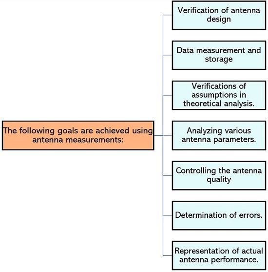
How antenna measurement is done?
As we have discussed in the beginning that the samples of the various parameters are recorded from a different location using the source antenna and the antenna under test. However, just by rotating the AUT at its original position various samples can be collected.
The received pattern will be sharp only in case when there will be a direct path between source antenna and AUT. And this can be achieved when the testing environment is free from reflections.
Thus, to achieve this the use of anechoic chamber in free space is used.
Basically, the anechoic chamber is an enclosed room whose walls, floor and ceiling use RF energy absorbing material in order to reduce the reflecting ability of the system. So, under the controlled environment, the antennas can be tested in a better way.
It is to be noted here that the absorbing material is used as a layer with a thickness of around a few wavelengths. But this material in the chamber is not present at the locations of the transmitting antenna and test antenna.
As we have previously discussed that antenna arrangement follows reciprocity theorem. Thus, the antenna which is under test can be a transmitting or a receiving one. However, generally, the antenna under test is a receiving antenna which collects the signal emitted by the source antenna.
So, on a general basis, experimentally the antenna measurements are classified as:
- Impedance Measurements
- Pattern Measurements
In impedance measurement, the intrinsic, input, self and mutual impedance are measured. While in pattern measurements, gain, beamwidth, polarization and radiation characteristics are measured. Here in this section, we will discuss antenna impedance measurement.
Antenna Impedance Measurement
The measurement of antenna impedance highly depends on the frequency of operation. Thus, on the basis of the frequency range, there are two methods of impedance measurement.
Basically, for low-frequency applications i.e., below 30 MHz, the bridge method is used for measurement. As against, for high-frequency range i.e., above 1000 MHZ, slotted line measurement is used.
Also, in the frequency range between 30 to 1000 MHz, ant of the methods can be used but that depends on convenience and equipment availability.
Let us now discuss each method to determine the impedance separately.
Impedance Measurement by Wheatstone bridge method
A wheat stone bridge is generally used to determine the unknown value of impedance by comparing it with known impedance. So, by using this method impedance at frequencies up to 30 MHZ can be determined.
The figure below shows the Wheat stone bridge arrangement where it is consists of 4 impedances in the 4 arms. Here the Za and Zb are ratio arms while Zc corresponds to variable arm impedance and Zd is the unknown impedance which is to be measured.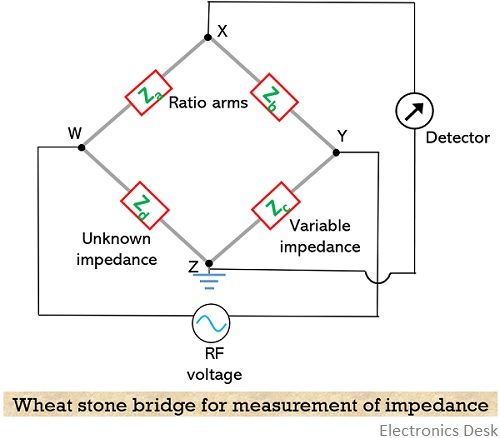
Under the balanced condition of the bridge, no potential difference would exist between points X and Z thereby providing a null in the detector.
So,
Here the bridge is in a balanced condition, in terms of both magnitude and phase. Therefore, rewriting the above equation in polar form, we will get,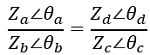
On simplifying![]()
Thus, both magnitude and phase balance conditions must be fulfilled.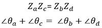
So, the value of unknown impedance Zd will be given as: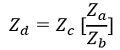
Therefore, whenever there is a need to determine the antenna input impedance then the antenna input terminal must be connected between the points W and X. It suits grounded vertical antennas of low frequency.
In order to have desired results, points W and Z must be grounded initially with respect to ground. Due to this reason, in the beginning, the bridge is balanced with the short-circuited or open-circuited condition.
Further during the operation, the unknown impedance is inserted at that particular arm and short is removed. Moreover, using the impedance equation, the unknown impedance is determined.
Impedance Measurement by Slotted line method
It is also known as a standing wave ratio method or standing wave method of impedance measurement. This measurement is based on the popular characteristics of travelling waves.
Basically, the method tells the idea of uniquely determining the impedance through voltage or current standing wave ratio and the separation distance between voltage or current minimum and the reference point of impedance.
It is widely used at UHF and microwave frequencies. Let us see how the method helps to measure the impedance.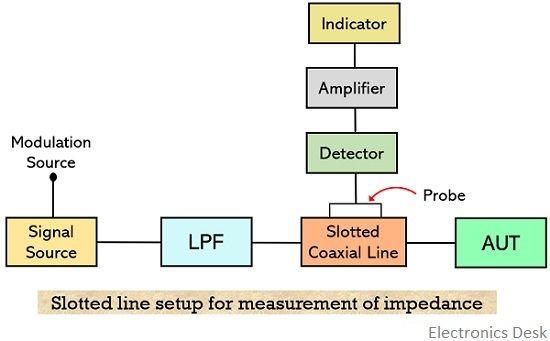
The figure shown above represents the connection of devices necessary to determine the impedance. So, all the devices must be connected in the same manner.
Here as it clear that at one side a single source is present while at the other side the unknown impedance to be measured is present.
We are aware of the fact that improper termination of the antenna with the feeding transmission line gives rise to standing wave along the transmission line.
So, a portion of the transmission line which is connected to the antenna is replaced by an axial slotted line over which a probe moves. Also, for measuring the voltage in order to get the impedance a crystal detector and a micro-ammeter is used.
Thus, at the various locations along the slotted line between the generator and the load, the probe is moved.
The movement of the detector probe leads to providing the reading in the microammeter which is noted down. This resultantly gives rise to a standing wave plot based in the readings.
It is to be noted here that the movement in the two consecutive points of Vmax and Vmin of the probe in the slotted coaxial cable are noted. Resultantly the ratio of the two will provide VSWR i.e., the input impedance.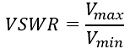
Another noteworthy point here is that the probe must be accurately inserted into the axial slot line so as to get proper sampling.
This is all about antenna impedance measurement. In the upcoming article will see another classification of antenna measurement i.e., pattern measurements.