Definition: “An-echoic” is a word that means “non-reflective“. Sometimes it signifies non-echoing or free of echoes. Anechoic Chambers are basically enclosed indoor rooms whose walls, ceiling, and floor are covered with a layer of absorbent that absorbs radio-frequency energy that helps to reduce reflections.
As it is an indoor chamber thus, for the small antennas it shows suitability for far-field measurements.
Content: Anechoic Chambers
Introduction
We have discussed in antenna measurements that the source antenna and the antenna under test is placed inside the anechoic chamber in order to measure the parameters of the antenna under test. Previously we have discussed that antenna measurement is necessary as it plays a crucial role in antenna designing.
However, this article focuses on anechoic chamber so, we will not go in detail regarding the measurement of the antenna. So, if you need to study more about antenna measurements you can see impedance measurement and pattern measurement.
Need for Anechoic Chamber
You must be thinking that what is the need to have an indoor chamber for the purpose of antenna measurement.
Basically, the anechoic chamber acts as an alternative to the outdoor range for measurements of the antenna.
We know that various factors are associated with outdoor arrangements of testing. This is because the outdoor environment where the testing is performed greatly affects the test results.
However, this indoor setup provides a secured and controlled environment that supports testing with minimal interference. This chamber is enclosed by microwave absorber walls that are formed by radiation absorbing material. The presence of absorbing material on the walls of the chamber reduces the chances of reflections thereby minimizing the waves interference effects.
The radiation absorbing material has carbon-impregnated foam that generates files shaped as an array of pyramids or wedges. This facilitates minimization of front face reflections.
What is Anechoic Chamber?
As we have discussed at the beginning itself the word an-echoic corresponds a non-reflective region. So, anechoic chambers are basically indoor rooms which possess non-reflective free space that provides a controlled laboratory environment for antenna measurements in all types of weather conditions.
This is considered to be a crucial block for indoor measurement purposes. It is regarded as a special room designed for absorbing either sound or electromagnetic waves. Also, prevents the waves from its surrounding to enter test area.
This causes the test area to get completely isolated from the interfering signals. Also, in order to improve the isolation, shielding is used, as shielded chambers suit better in case of electromagnetic compatibility measurements.
In case of measurements of antennas that possess large physical size, usually, a combination of the anechoic chamber with the outdoor range is provided by opening the end walls. Also, it is not necessary to apply absorbing material on the overall lining of the chamber. This provides measurement in compact antenna test ranges and far-field ranges.
Basically, in this indoor setup, the physically isolated structures prevent the entrance of the external waves by using acoustical filters and thick masonry walls. While internally the wave reflections are reduced to the least amount as possible by covering the interior with absorbing material.
- It is to be noted here that the absorbing material is now an integral part of antenna technology. This is so because it is used as an antenna for reducing the side and back lobe radiations, as well as in measurement ranges.
Generally, with the use of an ideal absorbing material, incoming waves at all frequencies and angle of incidence can obtain proper impedance matching.
Also, we have discussed earlier that the material is shaped in the pyramid or wedge-like structure, however, for normal incidence pyramid shapes are mostly preferred.
- Another noteworthy point over here is that the absorbing material provides reflection coefficient of -40dB at normal incidence at frequencies near 100 MHz. So, at low frequencies, the thickness of the material coated must be increased so as to get the desired reflectivity performance.
Types of Anechoic Chambers
The classification of the anechoic chamber is based on its design according to the geometrical optics techniques for reducing the specular reflections.
Let us discuss each one separately.
Rectangular Anechoic Chambers
In this type, floor, ceiling, end and centre parts of the side walls are covered with pyramids while the rest of the part is covered with wedges. This is clearly shown in the figure below: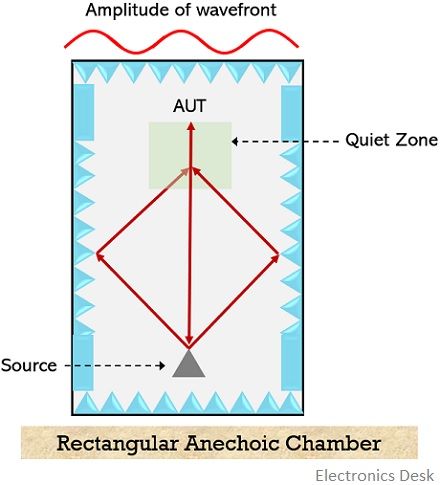
The antennas are placed on the vertical line of symmetry of the chamber. It is clear from the above figure that the source antenna is closer to one end of the wall but the test antenna is present at a little distance from the opposite sidewall.
In relative to dimensions, it is to be kept in mind that the length of breadth ratio of the chamber should be 2:1. Also, in order to have the least reflections within the chamber, the dimensions of the chamber must be such that the angle of incidence on the sidewalls should not be equal or more than 60°.
The source antenna inside the chamber should be carefully chosen so that the main beam is not illuminated towards floor, ceiling or sidewalls but is directed towards the test antenna.
The test antenna is generally considered to be of isotropic nature. As the reflections within the chamber are highly dependent on the angle of incidence even a very high-quality absorber cannot stop significant reflections when the angle of incidence is large.
Tapered Anechoic Chambers
Tapered chambers are generally used as an alternative to the rectangular chamber because for frequencies less than 1 GHz, there exist high-level reflections even with the excellent absorber.
The figure below represents the tapered type of anechoic chamber: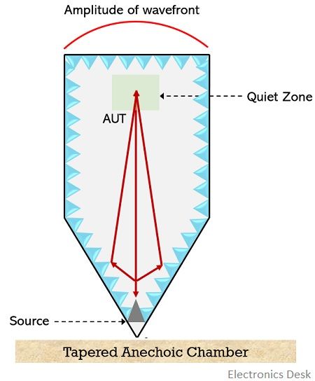
The structure of the tapered chamber is such that the lower portion possesses the shape of the pyramidal horn while the upper portion is in the form of a rectangle.
Here, the source antenna is present near the apex of the tapered region of the chamber where specular reflections occur while the antenna under test is present at the region of rectangular configuration.
At the tapered region, the difference in phase of the incident wave and reflected wave undergoes slow variations in the quiet zone thereby providing more planar wavefront in case of the rectangular chamber.
At higher frequencies, the source antenna is moved from the apex towards the rectangular section, so as to achieve the characteristics of the rectangular chamber. As against at low frequencies, the presence of source at the apex gives rise to reflections from the side walls. And in this condition, the minimal phase difference between the direct and reflected wave can be managed to achieve.
Hence, the wave reaching the test region is the vector sum of direct and reflected rays, thereby providing smooth amplitude illumination taper.
This is all about Anechoic Chambers.