Antenna Pattern Measurement is a way of determining the radiation pattern of the antenna under test i.e., AUT. Antenna pattern or radiation pattern graphically represents the radiation properties of the antenna with respect to the space coordinates.
For the measurement of antenna pattern more specifically, it can be said that it refers to the measurement of relative magnitude and phase of the electromagnetic signal transmitted by the test antenna.
Content: Antenna Measurements – Radiation Pattern
Introduction
In the previous article, we have discussed that antenna measurements correspond to the analysis of various parameters of the antenna to get the idea about the performance of the antenna. For this purpose, AUT is considered in conjunction with a source antenna that helps in determining system performance.
Previously we have seen that on an experimental basis, the antenna measurement is categorized as impedance measurement and pattern measurement.
The pattern measurement of the antenna is mainly associated with measuring the radiation characteristics of the antenna along with measurement of parameters such as gain, beamwidth, polarization etc.
A noteworthy point over here is that in case of highly directional antenna such as horn, the pattern measurement is done by scanning the region parallel to the side where the horn is facing up to a certain distance.
However, in this article, we will discuss the total spherical pattern measurement desired for a general class of antenna.
Antenna Radiation Pattern Measurement
We know that the radiation pattern of the antenna has radiation lobes. In case of an ideal antenna, there is only a single radiation lobe. However, as it known to us that no antenna is ideal, thus, the radiation pattern has major and minor lobes.
The major lobe of the antenna pattern represents the direction where there is maximum radiation. While the minor lobe corresponds to all other directions of the pattern and the minor lobes are also known as side lobes.
Basically, the radiation pattern of the antenna shows the field strength or power density exhibited at a fixed distance from the antenna in consideration with the direction. As the radiation pattern of the antenna is the three-dimensional characteristics thus the field intensity is necessarily measured for the overall spatial angles.
Thus, to accomplish this, the various angles in space must be specified. Generally, the space antenna is considered to be present at the origin of the spherical coordinate.
Let us discuss this more under the measurement procedure section.
Procedure for Pattern Measurement
We know pattern measurement setup must necessarily have two antennas. One is the antenna under test referred as a primary antenna while the other is the secondary antenna. And as the system follows reciprocity theorem so the radiation pattern will be the same for both the antenna thus out of the two any one of them can be the transmitting antenna while the other will be the receiving antenna.
Basically, there are two fundamental procedures for measuring the radiation pattern of the antennas. Let us understand each one separately.
Procedure I
In this procedure, the primary antenna is placed at a specific location and is of immobile nature. Whereas, the secondary antenna is placed at a certain distance from it. However, the secondary antenna is not stationary as it moves around the primary antenna maintaining that specific distance.
Generally, the primary antenna is the transmitting one while the secondary is the receiving antenna, but this condition is not necessary for the measurement to take place and this we have discussed above recently.
In case of the highly directional secondary antenna, it must be properly focused towards the primary antenna. This is so because in this condition the radiation pattern of the secondary antenna will only be affected by the primary one.
Further, at a different point on the circular path, the field strength and direction of the secondary antenna with respect to the primary one is noted down.
This helps in plotting the radiation pattern of the primary antenna in either rectangular or polar form.
Procedure II
In this method of radiation pattern measurement of antenna both primary as well as secondary antennas are placed at fixed positions separated by a sufficient distance. Again, under a general condition, the primary antenna is considered as the transmitting one while the secondary antenna is the antenna under test. Here the positions of the two antennas are fixed but the secondary antenna is rotated about the vertical axis.
The figure below represents the radiation pattern measuring setup: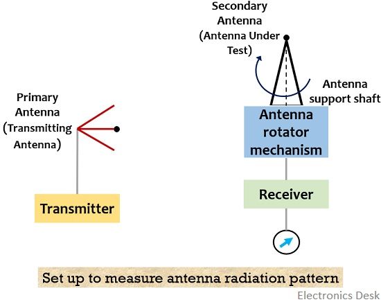
Here as we can see that the transmitting antenna is fixed while the test antenna is placed on a rotating shaft as this will help in rotating the antenna through rotator mechanism.
Now, during the rotation of the test antenna about the vertical axis, the primary antenna is fixed and is not rotated. So, when the transmitting antenna provides the illumination to the test antenna at different angles then field strength at various directions is noted down by stopping the rotation each time at some specific angle.
Sometimes by making use of pattern recorder even with the continuous rotation of the test antenna, the readings can be recorded. In this case, the antenna rotation is in synchronization with the motor-generator units.
Here we have discussed two procedures where the two antennas are operated differently. It is to be noted here that the first procedure is generally useful in low-frequency antenna measurement while the other is suitable for high-frequency antenna measurements.
The two major requirements of pattern measurement are as follows:
- Distance and
- Uniform Illumination
1. Distance: When we talk about the distance requirement then in order to get the desired far-field pattern, a sufficiently large distance must be maintained between the two antennas. This is so because if the distance is small then we will get near field pattern of the antenna.
However, for accurate pattern measurement, the plane wavefront must illuminate the antenna under test and only in case of sufficiently large distance, plane wavefront can be achieved.
Therefore, the distance between primary and secondary antenna should be specified as:
: r is the distance separating the two antennas,
λ is the wavelength and
d is the maximal linear distance of any of the antenna
The above equation is obtained on the basis that the difference in phase between the centre and the edge of the test antenna must not be greater than λ/16.
2. Uniform Illumination: Along with a properly large distance, to get accurate field pattern, the plane wave produced by the transmitting antenna must possess a uniform amplitude and phase over the complete distance of separation.
Here the reflections from the ground, buildings, trees, etc. must be greatly avoided.
Thus, from the above discussion, we can say that the pattern measurement of the antenna relies on the field strength of the antenna wrt direction. However, the distance and illumination requirement must be properly considered.
This clarification is very interesting!!!!
# I have a question about antenna impedance
{how to measure the impedance of a small antenna over a ground plane without cable detachment?}