Definition: Horn antenna is a type of antenna which is constructed when the end of the antenna is flared out or tapered in the shape of a horn. Horn antenna operates in microwave frequency.
These operate in ultra-high and super-high frequencies ranging between 300 MHz to 30 GHz.
It is generally considered as a waveguide whose one of the ends is widened out in the shape of the horn. Due to the flared-out structure of the antenna, there is greater directivity thus the emitted signal can be transmitted to longer distances.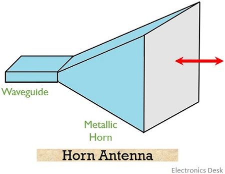
What is a waveguide?
We know that waveguide is a hollow tube that allows energy to get radiated in space when excited at one end and opened at the other.
It is to be noted that the amount of energy radiated by a waveguide is comparatively greater than the two-wire transmission line.
There is no central conductor present in the waveguide and can be either rectangular or cylindrical. It allows propagation of electromagnetic waves from an end to another. These are considered to be high pass filter as permits the propagation of high-frequency signals through it.
Content: Horn Antenna
Need of Horn Antenna
We know that the open end of the waveguide radiates energy, but only a fraction of incident energy is radiated by the waveguide and rest is reflected back by that open end. This is so because due to the open end, there exist poor impedance matching between the waveguide and space.
Also, diffraction at the edges of the waveguide results in the poor radiating ability of the waveguide. And so, the radiation pattern is non-directive in nature.
Thus, to overcome the disadvantages associated with the waveguide, its end is opened out in the form of an electromagnetic horn. This allows a smooth transition between the waveguide and space thereby offering better directivity to the radio wave.
By terminating the waveguide with a horn-like structure, the discontinuity existing between the waveguide and space, having impedance 377 ohms is eliminated.
This offers the incident energy to be radiated in forward direction thereby reducing the diffraction at the edges. Hence the directivity of the transmitting antenna is improved and with better gain.
To have higher antenna gain there must be a large antenna aperture. And for a given aperture size, high gain is achieved when the tapering is significantly long. Generally, the gain of horn antenna is around 20 dB.
Types of Horn Antenna
- Pyramidal horn: A type of horn antenna which is formed by flaring both the walls of the waveguide is known as pyramidal horn antenna. In pyramidal horn antenna generally, a rectangular waveguide is used and the flaring is done in the direction of both electric and magnetic field vectors. Here the flared structure of the waveguide resembles like a pyramid thus is named so.
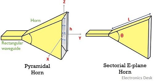
- Sectoral horn: In this type of horn antenna flaring is performed only along one of the walls of the waveguide. However, these are further classified as:
- E-plane: When one of the walls of the waveguide is flared along the direction of electric field vector is known as E-plane sectoral horn antenna.
- H-plane: When the wall of the waveguide is flared along the direction of the magnetic field vector then we call it H-plane sectoral horn antenna.
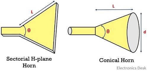
- Conical horn: The formation of a conical horn antenna is a result of flaring a circular waveguide. A circular horn antenna can be either conical or biconical in nature.
- Exponential horn: Exponential horn antenna has a curved side and sometimes referred as scalar horn antenna. It is called the exponential horn antenna because the separating distance between the sides rises exponentially as a function of length. These antennas offer constant impedance up to a large frequency thus there are less chances of internal reflections.
Working
Till now we have discussed that a horn antenna is a modified waveguide that is used for transmission of the signal.
We know that one end of the waveguide is excited then the field is generated. Generally, the fields in the waveguide as well as in free space propagate in a similar way. However, in case of propagation through the waveguide, the propagating field is constrained by the walls of the waveguide thereby the field fails to spread spherically while this is not the case with free-space propagation.
When the traversing field reaches the end of the waveguide then also it propagates in the same manner, however, due to Huygen’s principle now the waves begin to spread laterally. Thus, at the end of the structure, spherical wavefronts are achieved.
Basically, the region is said to be the transition region, where the guided propagation changes to free space propagation.
And as we know that the free space impedance is different from the impedance of the waveguide thus flaring of the waveguide is done to reduce reflections.
The flaring not only offers impedance matching but also results in higher directivity and narrow beamwidth thus we get the desired radiation pattern.
Design equation of Horn Antenna
Suppose we have an E-plane sectoral horn with a source that radiates cylindrical radiations as shown below: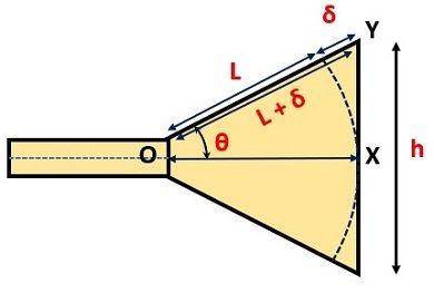
The electromagnetic horn gives rise to uniform phase front having a greater aperture in comparison to the waveguide. Thereby giving rise to higher directivity.
The uniform wavefronts the propagates in outward direction are cylindrical.
It is noteworthy here that as the wave propagates in a different direction from apex to aperture, thus there exist a difference in phase at the origin and the aperture.
Consider the path difference to be δ.
From the geometry of the above figure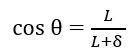
and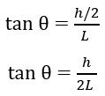
Therefore,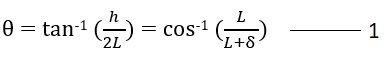
Considering right angle triangle OYX, and applying Pythagoras theorem,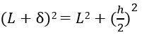
On simplifying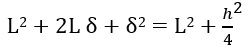
Since δ is small thus δ2 can be neglected.
Hence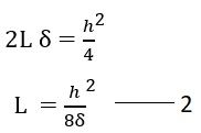
Therefore equation 1 and 2 are the design equations of the horn antenna.
Advantages
- These antennas offer easy construction as can be easily configured with a waveguide.
- The absence of a resonance element in the structure allows it to operate over a wide bandwidth.
- It provides good impedance matching.
- Horn antenna is highly directional in nature thereby providing higher directivity.
- It offers less reflections.
Disadvantages
- The directivity of the antenna is dependent on the flare angle.
- The dimensions of the flare must be sufficiently large and this sometimes makes the antenna bulky.
Applications
Microwave frequency operations that require moderate gain, use horn antenna. As we have already discussed that for higher gain the dimensions of the horn must be larger. Thus, it is preferred for moderate gain operations.
When we talk about high power gain operations then such applications use lens or parabolic antenna rather than horn antenna.
We know that parabolic reflectors require feeding element to excite them. Thus, the higher directivity offered by the horn antenna allows it to illuminate the reflector. Along with this, these antennas are also used in speed enforcement cameras, so as to avoid reflections that obstruct the desired response.
good information