Definition: A type of antenna which is formed by bending of a coil or uniform wire in the form of loop is known as a loop antenna. Basically, in loop antenna, the RF current-carrying coil is bent to various shapes like circle, square, rectangle, ellipse, etc.
Thus we can say it as a current-carrying coil bent in the form of loops of different shapes is known as a loop antenna. These antennas are known to be simple, inexpensive and versatile antenna and thus has a wide range of applications.
The bending of the wires into different shapes forms different types of loop antenna such as circular, rectangular, triangular, elliptical, etc.
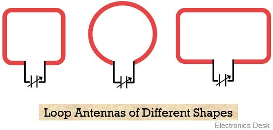
It is to be noted here that despite its availability in different shapes, circular type of loop antennas is widely used. The reason behind this is that circular loop antennas offer simplicity in construction as well as analysis. Thus is widely used.
Generally, loop antennas are referred as a radiating coil with any cross-section having single or multiple turns. When a loop antenna contains two or more turns then it is called a frame.
The operating frequency permitted by loop antenna ranges between 300 MHZ to 3 GHz.
Classification of Loop Antenna
Generally, loop antennas are classified as follows:
- Electrically small loop antenna: The type of loop antenna having a length of wire or circumference of loop less than one-tenth of wavelength is known as a small loop antenna.
Thus, here C < λ / 10
These types of antennas offer small radiation resistance having value even smaller than their loss resistances. So, it offers, poor radiating ability, thus is not considered as good radiators.
Due to this reason these are not used in transmitting applications. Therefore, find uses at the receiving sections, where having a good signal to noise ratio is more important than the efficiency of the antenna.
Irrespective of the shape of the loop, the field pattern of all the small loops is the same as that of infinitesimal dipole having maximum along the plane and null perpendicular to the plane of the loop.
- Electrically large loop antenna: When the circumference of the loop is approximately equivalent to free space wavelength then it is referred as an electrically large loop antenna. This means
C ̴ λ
In the case of large loop antennas, the field pattern is such that the null is in the direction of the antenna axis.
The increase in the perimeter or the number of turns in the loop electrically enhance the radiation resistance of the loop. This is so because, with the increase in the length, the circumference approximately reaches wavelength and in that case, the field pattern will vary and the maximum will shift from plane to the axis of the loop.
Sometimes the placement of high permeability ferrite rod within the circumference of the loop also increases the radiation resistance.
Direction-finding by Loop Antenna
Consider the figure of a single turn rectangular loop antenna:
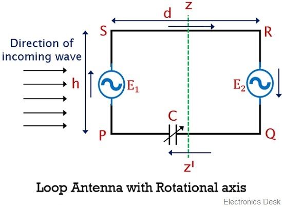
Here as we can see there are 4 arms of the loop. So, the horizontal arms (PQ and RS) act as a horizontal antenna while the vertical arms (PS and QR) act as a vertical antenna.
In the first configuration, when the plane of the rectangular loop is placed normal to the direction of vertically polarized incoming waves, then the voltage of equal magnitude will get induced in each of the vertical antennas. This induced emf’s are given as E1 and E2 for arm PS and QR.
Now, induced emf’s in each of the vertical arms, allow the flow of current inside the loop. However, the direction of the flow of currents inside the loop will be opposite.
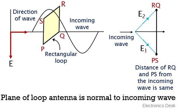
This is so because, when the incoming wave is normal to the plane then the vertical sides of the loop antenna are equidistant from the transmitter. So, the two currents are of the same magnitude but different polarity thus cancels each other.
Further, in the second configuration, the antenna is rotated by 90 degrees along the zz’ axis. So, after rotation, the plane of the loop will be along the direction of the incoming waves.
Now, in this case, the two vertical arms PS and RQ are separated by a certain distance of the length of the horizontal arm. Thus the emf induced in both the arms despite having similar magnitude will have a difference in phase.
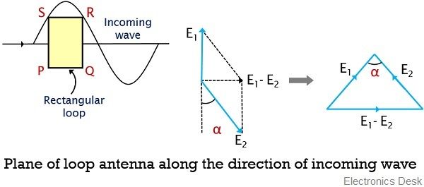
This is so because the incoming radio waves will reach one vertical arm of the loop somewhat earlier than the other. Thereby leading to generate a certain phase difference between the induced voltage E1 and E2.
Thus the overall induced emf around the loop will be equal to the difference of the induced emf’s (suppose α) of the vertical arms.
Hence the overall induced emf will be:
E1 – E2
Another noteworthy point over here is that for the other positions of the plane wrt to the incoming wave other than normal, there will be a certain distance between the two vertical arms. And in that case, the phase of the two induced emf will be unequal.
Thus maximal loop emf is achieved when the plane of the loop is in parallel orientation wrt the direction of the incoming wave from the transmitter.
Suppose θ represents the angle between the loop plane and the direction of incoming wave, then the induced emf in vertical arm will be:
E = Erms cos θ
When the loop plane and incoming wave are in the same direction, i.e., θ will be either 0⁰ or 180⁰, then maximal emf will get induced. While when loop plane and incoming wave are perpendicular to each other i.e., θ will be either 90⁰ or 270⁰, then the induced emf will be minimum.
Thus we can say that the emf induced around the loop antenna shows dependency on the orientation of the plane and incoming wave. Along with this, it also depends upon the vertical height of the antenna, wavelength, width of the loop and electric field intensity.
Applications of Loop Antenna
As we have already discussed that, loop antennas are majorly used for the purpose of receiving the signal. Thus these are mainly used in:
- Aircraft direction finders.
- In radio receivers for receiving high-frequency waves.
- Loop antennas are also used as ultra-high frequency transmitters.
- In RFID devices, to detect the position of the transmitter.
So, we can say, that loop antennas along with ease of construction provide the simplicity of operation, thus are widely used.