Definition: The input impedance of antenna is basically the impedance offered by the antenna at its terminals. It is defined as the ratio of voltage to the current across the two input terminals of the antenna. Generally, the antenna impedance is given as:
![]()
We have already discussed in our previous article that antennas are used in wireless communication in order to transmit the signal in the form of waves. It is designed to change electrical energy into the electromagnetic signals at the transmitting end. While electromagnetic signal back to electrical one at the receiving end.
So, it basically integrates the electric field and magnetic field in order to generate voltage and current so as to actuate electrical devices. Thus the antenna impedance at a point is also given as the ratio of electric field to the magnetic field at that particular point.
Hence we can say that the impedance provided by the antenna at its input terminal is known as antenna impedance.
We know that when a certain voltage is provided to any transmitting antenna then it generates current by following ohm’s law.
![]()
Here R represents the resistance of the input terminal of the antenna.
Further on considering the imaginary part, we will have
![]()
So, if we have a transmitting antenna that is radiating some power then impedance Z will be present behind it. This is known as the impedance of the antenna.
This impedance is a merger of resistance and reactance thereby forming a complex value.
Antenna Resistance
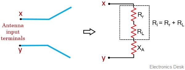
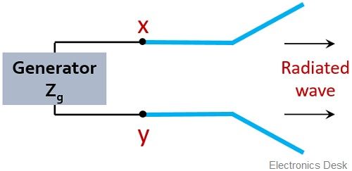
Suppose we have an antenna with input terminals x and y:
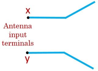
The power radiated by the input terminal of the antenna is given as: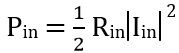
Since the total input power is the sum of radiated power and power loss,
Thus we can write it as:![]()
This is so because all the supplied power is not radiated as some amount of power is lost.
Hence the radiated power will be: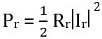
While loss / dissipated power will be: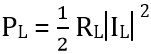
On substituting the obtained value of Pr and PL in eq 1, we will have: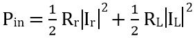
Also putting the value of Pin we will have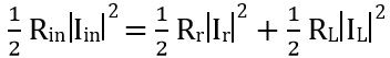
As the total current will be the sum of radiation current and loss current. Therefore writing the above equation as:
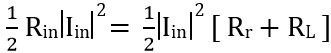
On simplifying
![]()
Thus we can say that the input resistance will be the sum of radiation resistance and the loss resistance. Therefore the figure below represents the input impedance of antenna:
Derivation of supplied power to the Antenna
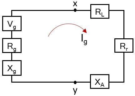
Suppose we have a configuration given below:
Here the two input terminals x and y of the antenna are connected across a generator.
One must note here that the generator will also have some internal impedance. So, consider the impedance of the generator be Zg.
We know that the impedance is given as:
![]()
Therefore
![]()
- Here Rg denotes the resistance of the generator
- While Xg denotes reactance of the generator
So, drawing the equivalent circuit of the generator antenna configuration given above:
For transmitting antenna, the impedance will be given as
![]()
- Here ZA is the impedance of the antenna,
- RA is the antenna resistance,
- XA denotes antenna reactance
The resistive part of the antenna which we have already derived is given as:
![]()
Let us now consider the Thevenin’s equivalent circuit shown above in order to determine the power delivered to Rr for radiation and the power dissipated in the form of heat in RL.
So, firstly we need to determine the current within the loop itself,
Therefore, by ohm’s law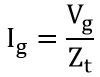
Here Vg is the maximum generator voltage while Zt denotes the total impedance present in the loop. Thus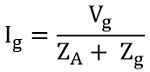
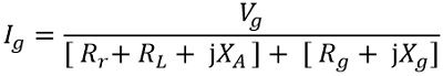
Further on simplifying,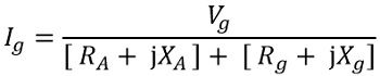
Since RA = Rr + RL
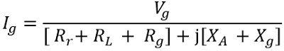
Therefore, we will have
Further
So, considering the magnitude form
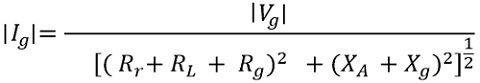
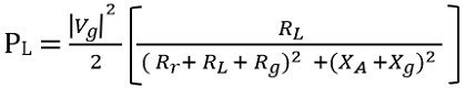
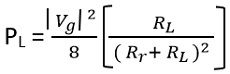
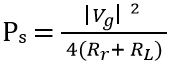
Thus we can say the radiation power Pr will be
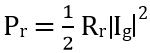
So, on substituting the value of Ig
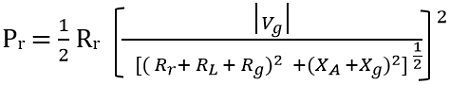
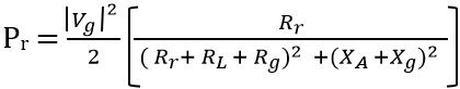
Thus the power by the generator to the antenna for radiation will be
The dissipated power
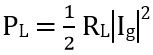
Therefore
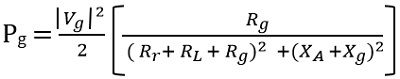
Also, the power dissipated on the internal resistance of the generator will be given as:
The condition of maximum delivered power to the antenna is achievable in case of conjugate matching. This means
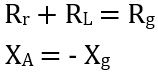
So, we will have
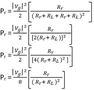 Similarly
And
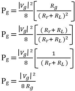
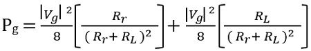
It is noteworthy here that the generated power must be equal to the sum of radiated power and the dissipated power in the form of heat.
![]()
So, on substituting
The supplied power by the generator
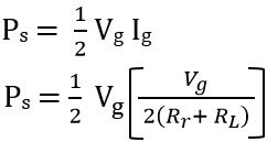
Therefore,
So, we can say the overall power generated by the generator is the sum of the power dissipated by the internal resistance of the generator and the power supplied to the antenna, in case of conjugate matching.
While, out of the overall power which is supplied to the antenna by the generator, a part is radiated utilizing radiation resistance, while the rest is dissipated in the form of heat. This dissipated power in the form of heat alters the efficiency of the antenna.