Definition: V antenna is a type of long wire antenna whose structure is designed in the form of a V. This is the reason it is given the name V antenna.
It operates in the high-frequency range between 3 to 30 MHz.
Basically, it is said to be an enhanced version of a long wire antenna that provides higher gain and directivity than long wire antenna. It is generally a resonant antenna that provides bidirectional radiation. However, proper impedance matching leads to provide a non-resonant antenna also that produces unidirectional radiation.
Content: V Antenna
Need for V Antenna
We have already discussed previously that in long wire antenna the length of the conductor is generally greater than half wavelength. More specifically, the length is in the multiple of λ/2.
However, the major concerning factor in case of a long wire antenna is that the directivity of the antenna decreases when the length of the conductor increases beyond a wavelength. So, to eliminate the disadvantage associated with the long linear conductor, the lengthened arm of the long wire antenna is bent in V-shape.
This tilted antenna offers high gain and directivity and is used for fixed frequency use in the high-frequency band.
Thus, we can say this antenna is a modified form of a long wire antenna that offers better characteristics than the long wire antenna.
Construction
A V antenna is a combination of two long wire antennas that are joined in the form of a horizontal V structure. The excitation to this antenna is provided at the apex using feed lines. And the two wires of the V antennas are referred as legs.
The figure below shows the structure of V antenna: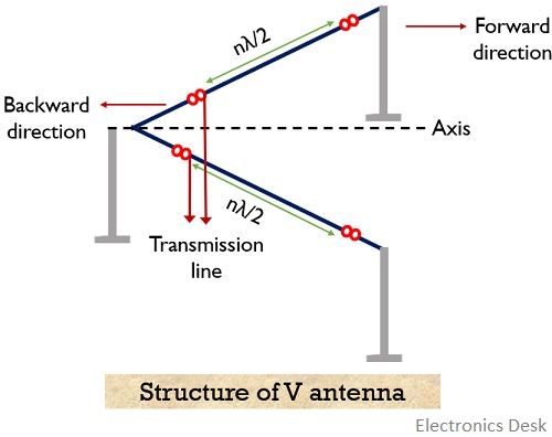
The arrangement shown above is resonant type V antenna as the two ends of the antennas are non-terminated.
As we can see here that the feed line to the antenna is provided at the joining angle of the two legs. This angle is known as apex. It is denoted by α.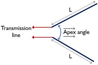
In comparison to a single long wire antenna, the gain offered by it is 2 times more.
In case of these antennas, if the length of each leg is 8λ, then it can provide a gain of about 12 dB. It is to be noted that the apex angle shows dependency on the length of the leg. Thus, for the length of each leg of about 2λ to 8λ, the apex changes between 36° to 72°.
Working of V Antenna
When a V antenna is excited at the apex then due to the externally applied sinusoidal signal, the charge carriers experience attraction and repulsion according to the polarity.
This cumulative action of the charge carriers gives rise to the varying electric field. Thus, the signal from an end to the other is radiated through the legs of the antenna.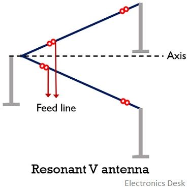
A crucial point to discuss over here is how the two legs of the antenna are excited to have high directive gain.
So, basically, while providing excitation to the antenna, the two legs are excited with signals that are 180° out of phase. This will lead to provide high gain and directivity.
The reason behind this is that when the apex is two times the angle of the cone of maximum radiation of each wire in the axial direction. Then the two cones will produce summed up result along the axis, bisecting the apex of the V antenna.
Therefore, in this case, the maximum lobe of radiation will be produced. And in this way, this antenna provides high gain and directivity. This is so because the radiation of each leg that is directed in the opposite direction will get cancelled out and those directed in same directions will get added up.
Thus, with the increase in the length of the legs of the antenna, the directivity and gain will also improve.
This leads to providing sharper bidirectional radiation pattern than a long wire antenna of similar length. Therefore, it is said that the V antenna offers twice the gain than that of the long wire antenna.
Till now we have discussed the resonant type of this antenna that provides bidirectional radiation pattern.
However, in order to have a unidirectional radiation pattern, we can have a non-resonating V antenna. A non-resonant type can be formed by terminating the legs of the antenna with resistive load with a value equal to its characteristic impedance.
The figure below shows the non-resonant V antenna:
Radiation Pattern of V Antenna
The figure given below is representing the radiation pattern for the resonant type of V antenna: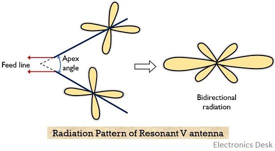
Now, have a look at the radiation pattern of the non-resonant type of antenna, showing unidirectional radiation pattern: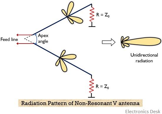
Previously, we have also discussed antenna array and various type of antenna arrays. There we have seen that to enhance the directivity multiple antennas are arranged to form a single system.
Likewise, the directivity of V antennas might also be increased by arranging to form an array. So, in this array, the elements will be only V antenna.
In the case of a vertical arrangement, the two or more antennas can be stacked one above the other. While in a horizontal manner these can be arranged in broadside.
A noteworthy point over here is that no reflector is used in case of the array with elements as V antenna.
Advantages
- The low cost of the V antenna is one of its greatest advantages.
- It offers high bandwidth.
- It is quite easy to construct.
- The offered directive gain is high.
Disadvantage
- A resonant as well as non-resonant both provides side lobes of great strength.
- The non-terminated ends of the antenna give rise to standing waves.
- It needs quite a large space for installation.
Applications of V Antenna
These antennas have their maximum applications in radio communication for commercial purpose. Also, their high gain and directivity support long-distance communication at a fixed frequency.