Previously we have discussed antenna array under various sections including its need, working, advantages, limitations along with applications.
We know that an antenna array is a single system formed by arranging various antennas in an appropriate manner. Basically, proper spacing and proper phase must be provided to the antennas when configured as an array. Whenever antennas transmit a signal to a longer distance then it is necessary that they must possess high directive gain because most of the time the signal distorts while propagating from an end to another.
A single antenna despite having good directivity somewhat fails to transmit the signal to the receiver without losses. This is the reason the antenna array is used. The classification of the antenna array is generally based on the orientation of elements within it. This means the way in which various antennas are placed in the arrangement classifies the antenna array.
Content: Types of Antenna Arrays
Broadside Antenna Array
A type of arrangement of multiple identical elements that are placed parallelly along the line normal to the antenna axes forms a broadside antenna array. It is known to be a practical antenna array configuration which is most widely used.
The figure below represents the broadside arrangement of antenna array:
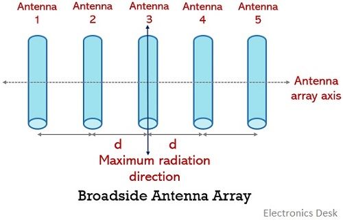 In this type of arrangement, the elements are present horizontally at equal distance from each other and each element is fed with the current of same magnitude and phase.
In this arrangement when the elements are excited then maximal radiation emission occurs from the broadside (i.e., the direction normal to the array axis) while the little amount of radiation is emitted from the other directions. Thereby providing a bidirectional radiation pattern. The reason for its bidirectional radiation pattern is that it radiates in both direction along the broadside. Thus, we can say, a broadside arrangement is the one whose principal direction of radiation is normal to the array axis as well as the plane of element placement.
The figure below represents the radiation pattern of the broadside antenna arrangement: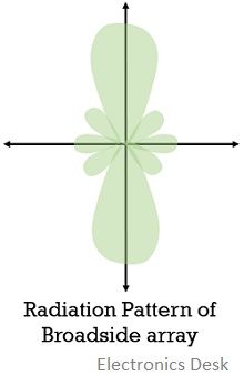
This means for horizontal alignment of the elements there will be a vertical radiation pattern.
If we want to convert the bidirectional radiation pattern into the unidirectional radiation pattern then this can be done by placing a similar array at a distance of about λ/4 behind this array and exciting the replica array with a current having phase lead of 90°.
Generally, the number of elements in the arrangement shows dependency on space available along with the need of beam width and cost. While the length of the array is taken between 2 to 10 λ.
Sometimes a reflector antenna is used in conjunction with the broadside array as this reflector helps to reflect the back transmitted wave thereby adding the minor lobe to the major lobe. This improves the gain and directivity of this type of antenna and provides a unidirectional radiation pattern.
These generally find applications in overseas broadcasting systems.
End-Fire Antenna Array
An end-fire array has a similar arrangement of elements as the broadside arrangement but the crucial difference between the two configurations lies on the way of excitation. In end-fire array, the elements are fed out of phase generally 180°, while in case of broadside each element is fed with the current of the same phase.
It is such an arrangement whose maximum radiation is obtained along the array axis.
The front view of the physical arrangement of elements in the end-fire array is shown below:
Basically, this whole arrangement of the identical elements is excited with the current of equal magnitude but there is a continuous variation in the phase along the line in order to have a unidirectional radiation pattern.
More simply, it can be stated in a way that, the difference in phase must vary progressively similar to the distance between the elements.
Thus, we can say that an end-fire array offers a unidirectional radiation pattern where the maximal radiation is achieved along the direction of the axis of the array. The radiation pattern is shown below: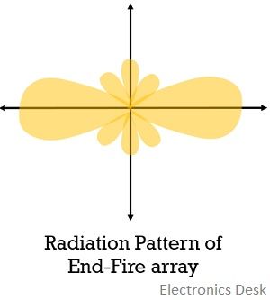
In this arrangement, the distance between the elements is generally taken as λ/4 or 3λ/4.
These arrays suit low, medium and high-frequency ranges and majorly used in case of point to point communication.
Collinear Antenna Array
The name itself is indicating that it is an arrangement that allows the placement of various antenna elements in a single line from an end to another. This means that here the various elements are stacked one behind the other in a single line.
This arrangement can be either of vertical or horizontal orientation. The figure below shows the collinear array with a horizontal arrangement: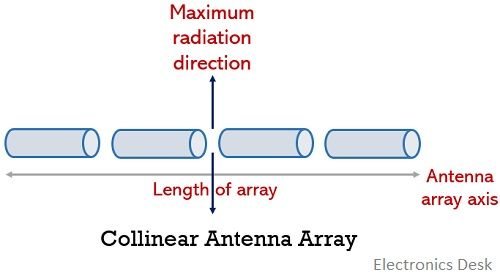
Here also the excitation is provided with currents of the same magnitude and phase to all the elements. Like broadside array, this also offers radiation in the direction normal to the axis of the array. Hence its radiation pattern is somewhat similar to the broadside array.
However, this array offers circular symmetry across the major lobe and thus facilitates omnidirectional radiation from itself.
This arrangement offers maximum gain when the elements are spaced at a distance of about 0.3 to 0.5λ, but this leads to cause constructional and feeding problems in the array. Therefore, the elements are placed closer to each other.
The radiation pattern of the collinear array: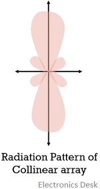
It is to be noted here that with an increase in the length of the array the directivity also increases.
Generally, 2 elements collinear array is mostly used as it supports multi-band operation.
Sometimes some applications use a combination of broadside, end-fire and collinear arrays as this increases the gain and directivity to a very high range.
Parasitic Array
Parasitic arrays are the multi-element arrays that provide high directive gain without even feeding each element of the array. This antenna array helps to deal with the problem of feedline by not providing direct excitation to each and every element of the array.
Its basis of operation is feeding some elements of the antenna array parasitically. The figure below shows the parasitic arrangement of antennas: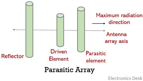
We have seen that in all the above-discussed types of antenna array excitation to each element is directly provided. But in the parasitic array, the arrangement supports exciting only the driven element directly while the other elements are excited parasitically.
The elements which are not fed directly are known as parasitic elements and these derive power from the radiation emitted by the driven element present near to it.
This means parasitic elements are excited through electromagnetic coupling because the driven element is present near to it.
This simply means that parasitic elements of the antenna array are not excited directly and indirectly uses the excitation provided to the driven element.
It is to be noted here that the induced current in the parasitic element due to the driven element relies on the distance between these two elements along with their tuning.
Generally, a separation distance of about λ/4 and a phase difference of 90° between the driven and parasitic elements provides a unidirectional radiation pattern.
The radiation pattern of this array is the result of reflector behind the driven element that adds the back-reflected waves to the forward wave.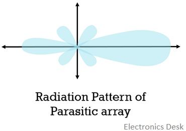
The best example of a parasitic array is Yagi-Uda Antenna.
These antenna arrays operate in the frequency range between 100 MHz to 1000 MHz. It exhibits unidirectional radiation pattern in the direction from driven to parasitic element and possesses high directive gain.