Antenna Gain Measurement is a crucial aspect of antenna measurement. The reason behind this is that the gain of the antenna plays a very important role in predicting the performance of an antenna.
Due to this reason measurement of the gain of the antenna is necessary.
Content: Antenna Measurements – Gain
Introduction
Previously we have discussed that antenna measurement is done to test the performance of the antenna system.
In the impedance measurement, we have seen that with the help of two separate methods, the impedance of the antenna can be determined. As against, in radiation pattern measurement, the radiation characteristics of the antenna is measured.
In impedance as well as radiation measurement we have seen that a test antenna and a source antenna (reference antenna) is considered. Also, either of the two can be taken as transmitting or receiving antenna for the purpose of measurement.
In this article, we will discuss, the measurement of antenna gain.
What is Antenna Gain?
Gain is a fundamental parameter of the antenna. It corresponds to the ability of the antenna to either direct the radiated power of the antenna in a specific direction or efficiently receive the incoming power from a specific direction.
It is defined as the ratio of maximum radiation intensity of the test antenna to that of the reference antenna where the input power is the same.![]()
This means to determine the gain, the actual or test antenna is compared with the reference one.
However, if we consider the directivity of the antenna then it is defined as the maximum radiation intensity to the average radiation intensity of an ideal isotropic antenna.![]()
Hence, in directivity measurement, comparison between two antennas is not taken into consideration.
So, the gain of an antenna with respect to an isotropic antenna:![]()
: G0 denotes the gain of an antenna with respect to an isotropic antenna,
D represents the directivity and
α is a constant that shows the effectiveness ratio whose value lies between 0 and 1.
It is to be noted here that, in high-frequency antennas, the losses are considered to be negligible thereby possessing 100% efficiency. Thus, α =1, so the value of measured gain is almost equivalent to the directivity.
Methods of Antenna Gain Measurement
In the previous section, we have seen that to determine the gain of actual antenna a comparison from the reference antenna is required.
So, there are various methods by which the measurement of antenna gain can be done. However, the use of the methods is categorized on the basis of frequency of operation.
Suppose if the antenna is operating above 1 GHz, then its gain is measured by free space ranges. At low frequencies, as the wavelength is longer so free space conditions will not be easily achievable. Thus, between 0.1 to 1 GHz, ground reflection ranges are used.
So, according to these two specified ranges, there are two standard methods used for antenna gain measurement. These are as follows:
- Gain transfer or Direct Comparison Method
- Absolute Gain Method
Basically, in free space range, the contributions from the surrounding environment of the system get suppressed. While reflection ranges generate constructive interference in the region of the practical antenna.
Here in this article, we will discuss how the gain of the antenna is measured using these methods.
Direct Comparison Method
We have already discussed in the beginning that for measurement of gain, a comparison between two antennas is made. Thus, the technique of direct comparison is used.
In this method of gain measurement, comparison between signal strengths of the unknown gain antenna and the standard gain antenna is made.
The figure below represents gain measurement by comparison method: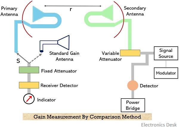
Basically, the standard gain antenna is the one with known gain. The standard antenna and test antenna together form an arrangement of the primary antenna. While the secondary antenna in the arrangement is simply an arbitrary transmitting antenna with unknown gain. This is clearly shown in the above figure.
- It is to be kept in mind that a considerable distance between standard and test antenna is maintained so as to avoid the chances of coupling or any type of interaction. Generally, an electromagnetic horn antenna is used as a standard gain antenna.
Also, as discussed in the pattern measurement that the distance requirement of the arrangement is such that r≥2d2/λ. So, the distance between the primary and secondary antenna must be properly maintained.
As standard and test antennas are acting as a unit thus to have appropriate matching with the load, an attenuator pad is placed at the receiver input.
- It is to be noted here that during the whole measurement there must not be fluctuation in the frequency of the power radiated towards the primary antenna. So, to ensure this, power level indicating device or power bridge is used at the transmitter.
Let now see what procedure must be followed to determine the unknown gain through the direct comparison method. The steps are as follows:
- Initially, the standard antenna with a known gain is connected to the receiver using the switch S and it is directed towards the direction of maximal signal intensity of the transmitting antenna (i.e., secondary antenna). With the properly applied input to the secondary antenna, reading of the receiver is noted. Along with this, the reading of the attenuator dial (W1) and power bridge (P1) is also noted down.
- Now, the switch is removed from the standard antenna and with the help of same switch connection of the test antenna is made with the receiver. Further, the reading of the attenuator dial is adjusted to get the same reading on the receiver as it was in the case with the standard antenna. Let the dial setting be W2 and power bridge reading is P2.
So, on this basis there will be two cases:
Case I: If P1 = P2, then gain of the test antenna will be:![]()
In decibels,![]()
Case II: If P1 ≠ P2, then the actual power gain of test antenna will be the product of Gp and P1/P2. So, let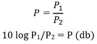
Power gain,![]()
On substituting the value of Gp: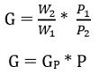
In decibels,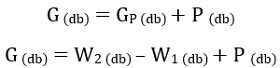
This is the gain of the test antenna. In this way, by the comparison method, the gain of the antenna is determined.
Absolute Gain Method
As we have discussed in the previous section that the standard gain antenna is the one whose gain is already known or calibrated. However, we can calibrate the gain using two or three arbitrary antennas.
The figure below represents an arrangement of two identical antennas for absolute gain measurement: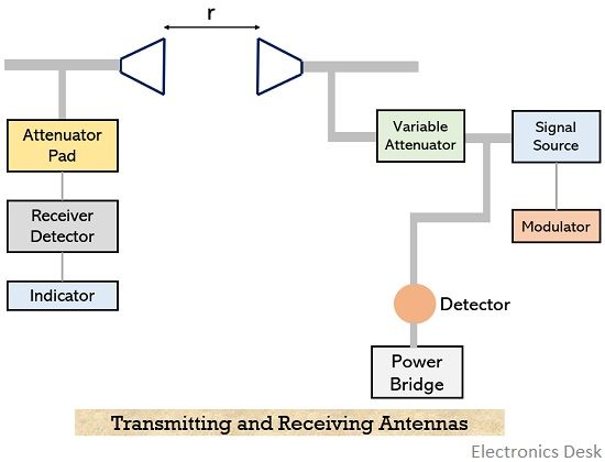
Suppose the two antennas (transmitting and receiving) are separated at a distance r. Here, Pt and Pr represent the transmitted and received power respectively. While Aet and Aer are the effective apertures of transmitting and receiving antennas.
As the two antennas are identical. Therefore,![]()
By Friis’s transmission equation,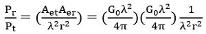
Thus,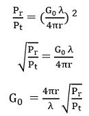
While if we consider the effect of direct and indirect rays in case of ground reflection then,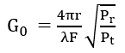
: F is the propagation constant due to interference.
From the above equation, it is clear that the power transmitted by the transmitter and received by the receiver is measured, then for the known value of separation distance and wavelength, the gain of either antenna can be determined.
Hence in this way by using any of the above-described methods. The gain of the antenna can be measured.