Definition: A broadband antenna that is designed to provide such electrical characteristics that vary repeatedly in a periodic manner with logarithmic of the frequency of operation is known as Log Periodic Antenna.
This means in this antenna; the impedance and radiation pattern are the factors that are logarithm function of the frequency.
The range of operation offered by this antenna lies between 30 MHz to 3 GHz.
Content: Log Periodic Antenna
- Introduction
- Construction
- Working
- Radiation Pattern
- Characteristics
- Advantages
- Disadvantages
- Applications
Introduction
It is a multi-element antenna that offers good directivity over a wide range of frequency of operation.
Basically, the type of antenna that is defined on the basis of angles only, is categorized as a frequency-independent antenna. In such cases, the impedance, as well as the radiation pattern both, do not show dependency on frequency.
This simply means that the impedance and pattern should remain invariable over a range of frequency.
So, in such a case, the structure of the antenna should be adjusted (either expanded or compressed) proportionally with the wavelength. While, for a non-mechanically adjustable structure, there must be proportionality of active or radiating region with the wavelength.
These antennas are said to be a class of antenna rather than simply being an antenna as they possess many different physical appearances. Like, planar, trapezoidal, V slot, zig-zag, dipole etc.
However, generally, log periodic dipole array finds a wide range of uses.
Construction
The log periodic antenna is constructed by the use of various half-wave dipole elements with a gradual increase in the length.
The structural geometry of the log periodic antenna is designed in a way that the electrical properties of the antenna must show periodic repetition with the logarithm of the frequency.
In a log periodic dipole array, multiple dipoles of different length and spacing are placed together. Also, the external excitation to the antenna is provided by the use of a balanced transmission line. This transmission line is transposed between the adjacent terminals of the dipole.
The connection of the feedlines is made either at the narrow end or apex of the array.
It somewhat resembles like Yagi-Uda Antenna as it is also a multielement antenna comprising of the half-wave dipole antenna.
The antenna elements are mounted on a single line along with a support boom. However, the way in which the two operate, are quite different.
We have seen that the addition of elements in case of Yagi-Uda antenna, provides an increase in gain and directivity. As against, in log periodic dipole array, the increase in the number of connected elements improves the frequency response or bandwidth that is offered by the system.
Working of Log Periodic Antenna
An antenna whose impedance acts as the logarithmically periodic function of the frequency of operation is known as log periodic. Also, the electrical properties like radiation pattern, directive gain, beamwidth, beam direction also undergo similar periodic variation.
In log periodic dipole array, there is a gradual increase in the length of the elements from point of feed to the other end, keeping the angle α constant. The increase in the length of the elements along with the spacing between them in wavelength should be so adjusted that there must be certain ratio in the dimensions of the adjacent dipoles.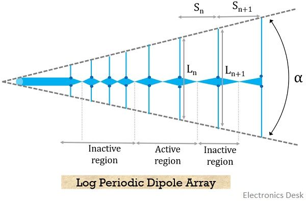
The parameter that defines here the relation between the length of the antenna elements and spacing between adjacent elements is called design ratio or scale factor. This is denoted by τ. It is sometimes referred as periodicity factor, having a value less than 1.
The length of the dipoles (L) and spacing (R or S) between them are related in the following way:![]()
Thus, is given as:![]()
Sometimes written as:![]()
While it can also be written in terms of another constant K, given as:![]()
So, due to this, the two ends of the dipoles will be present along two straight lines, meeting at angle α at one end while converging at the other end of the structure.
The value of α is generally 30° with τ = 0.7.
As it is clear from the structure that there is repetitiveness in the structure of the antenna that leads to provide repetitive behaviour of characteristics.
It is to be noted that if a plot between input impedance and frequency is drawn, then there will be repetitive variation. But if the plot between impedance and log of frequency (rather than just frequency) is drawn then the same variation will be periodic.
This means that we will get similar cycles of variations. This is shown below: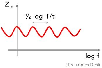
But a point to be kept in mind that, though we have represented sinusoidal waveform over here, it is not necessary that the variation is sinusoidal all the time. This means it’s just that each cycle will be identical to the preceding one.
Operation
A log-periodic antenna operates only in the active region rather than the whole structure. The various region of LPDA is classified as:
- Transmission line region: In this region of the structure of LPDA, the length of the elements is shorter than the half-wavelength (i.e., resonant length). These elements provide high capacitive impedance. Also, the spacing between the elements is small.
The current flowing through the elements in this region is of small magnitude and leads the supplied voltage by 90°. Thus, the small current through the element results in small radiation in the backward direction.
- Active region: This structural region of the LPDA has element length equal to half wavelength and offers resistive impedance. Here the current through the element is large and in phase with the supplied voltage.
Also, sufficiently large spacing exists between the dipoles. This is the region which is responsible to provide maximum radiation, by producing large resultant field towards the left and a little towards right.
It is to be noted here that, the frequencies where the length of the longest and shortest dipole is λ/2 is said to be the cut-off frequency.
So, for maximum frequency, the active region will be towards the apex, for intermediate frequency, the region will shift towards the middle region of the structure. While for minimum frequencies it will be near the region of longest elements.
This means that for LPDA, the phase centre shifts from one end to the other according to the shift in frequency from lowest to highest.
- Reflective region: The region having elements with length greater than resonant length (i.e., λ/2) becomes the inactive region. Thus, the impedance is inductive in nature that leads to generate a current that lags the supplied voltage.
It is to be noted here that this region receives very small voltage from the transmission line. This is so because the active region attracts and radiates the maximal radiation.
Thus, this region offers large reactive impedance to the line, so even if a small amount of wave that incidents on it from the active region then it gets reflected in the backward direction.
Radiation Pattern
These antennas offer bidirectional as well as unidirectional radiation pattern depending upon the log periodic structures. Basically, a structure with a single active region, there will be a unidirectional radiation pattern. But if there exist two active regions, there will be a bidirectional radiation pattern.
Characteristics
- The excitation to the LPDA is provided at the shorter length side in case of the single active region while at the centre in case of two active regions log periodic.
- To have a unidirectional radiation pattern, the structure must radiate towards the shorter element (i., left direction) and negligible towards the right.
- The transmission line inactive region must possess desired characteristic impedance with very small or negligible radiation.
- In the active region, to have strong radiation, the magnitude and phase of the currents must be proper.
Advantages
- It offers a compact structure.
- It provides adjustable gain according to the requirement.
- These offer negligible loss of power when terminated.
Disadvantages
- The mounting platform must be of sufficient strength to hold the elements.
- It is quite expensive than other antennas.
Applications of Log Periodic Antenna
It is used majorly for high-frequency communication purposes. Also, it is used for TV signal reception and for signal monitoring applications.