Adcock Antennas are basically arrangements of multiple vertical antennas in space-separated at some specific distance. It was proposed by an Engineer from British origin named Lient Adcock in 1916. Thus, so this antenna was named after him.
Adcock antennas are used for the purpose of transmission or reception of directional radio waves. However, at the initial level, it was majorly used for the purpose of signal reception.
It acts as a fundamental component of radio navigation systems.
Content: Adcock Antennas
What is Adcock Antenna?
In the simplest form, Adcock antenna arrangements have 2 vertical antennas which are place separated with some small distance apart.
Consider the figure shown below representing a simple form of Adcock antenna: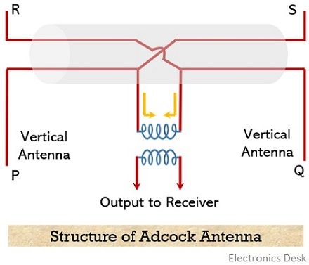
For vertically polarized waves, it operates the same as a loop antenna. This is said in regard to the fact that similar to the loop antenna, here also, the resultant current in the Adcock antenna is equal to the vector difference of the induced voltages in the two vertical antennas placed above the ground.
But the horizontally polarized skywaves reaching the horizontal parts of the antenna gets cancelled because of having same magnitude and phase.
Basically, in such arrangement, a metal tubing is used inside which the horizontal wires are placed. This tube acts as a shield for the wires towards the incoming radio waves.
This makes the Adcock antenna insensitive to horizontally polarized waves. And thereby making it free from errors related to polarization.
This signifies that the circuit arrangement of the Adcock antenna causes it to exhibit a nature which is free from the effect of horizontally polarized waves coming downwards.
Comparison with Loop Antenna
In Adcock antenna with proper shielding and balancing, for frequencies more than 5 MHz, the desired bearing can be achieved up to 160 km of distance. However, when the same conditions are considered for loop antenna then it gets completely failed.
But, as we know that a loop antenna has multiple turns, whereas Adcock antenna possesses long antennas with no such turns. Thus, the approximate height of the Adcock antenna is the same as a single turn of the loop antenna. So, while considering all the turns of the loop antenna, in terms of induced voltage, Adcock antennas are somewhat inferior to loop antennas.
Hence, in order to have better-induced voltage than loop antenna, Adcock antennas are needed to have a very large physical size so as to get comparable output.
Along with this, another noteworthy point over here is that a loop antenna exhibits moderate internal inductive impedance and can be easily tuned to resonance with suitable turns in loop and use of variable capacitance with least possible loss.
While the Adcock acts as an energy source possessing high internal capacitive impedance. Thus, in order to tune it to resonance, a high inductance coil is to be used but this will add a large amount of loss to the circuit.
Various Arrangements of Adcock Antenna
As we have discussed in the previous section, that the simplest Adcock includes 2 vertical antennas in the arrangement.
However, these two antennas can be arranged in different ways in order to fulfil the purpose of direction-finding at different frequencies.
Generally, in the frequency range between 2 to 30 MHz, due to the horizontally polarized waves, there exists polarization error in a loop antenna. Thus, to overcome this, elevated H-type Adcock antennas are used.
This is represented in the figure below: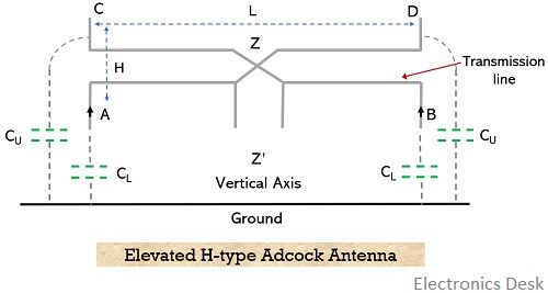
Here the vertical dipoles are separated with the help of horizontal support where a cross-connection of the transmission lines is formed at the centre. It is to be noted here that with the increase in the distance between the ground and lower limbs of the antenna structure, there is a decrease in polarization error.
Further, the figure below shows the upper half portion of the elevated H-type antenna: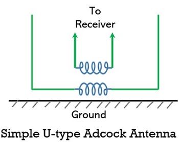
As we can see in the figure above that the horizontal part of the structure is very close to the ground.
On considering the ideal condition of earth as a perfect conductor, the polarization will be zero. However, as we know that earth is not a perfect conductor, therefore, horizontal polarization will induce some voltage in the horizontal part and this results in giving rise to polarization error.
However, with the use of proper shielding in the horizontal part of the structure, polarization error can be reduced represented in the figure below.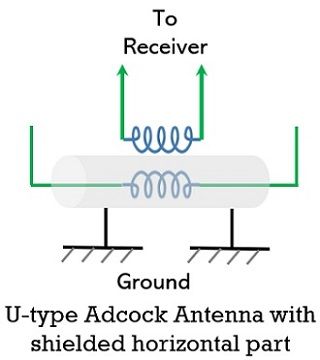
But sometimes the horizontal part of the Adcock arrangement is buried underground.
- It is to be noted here that when the horizontal part of the arrangement is unshielded then polarization is somewhat really high. But in the shielded condition, the polarization of the Adcock antenna is reduced to half. While, if we bury the horizontal part of the arrangement into the ground then this reduces the polarization more.
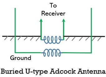
However, in this case, the amount of polarization error shows dependency on the depth up to which the horizontal part is buried, along with the earth’s conductivity and frequency.
Moreover, two other types of Adcock antennas are generated which are regarded as a modified version of elevated H-type Adcock. The balanced Adcock antenna is shown below: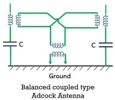
This is formed by reducing the length of lower vertical limbs of the arrangement and this facilitates reducing the distance between the earth and the horizontal part of the structure. Also, separate capacitances are used for compensating impedance. And this is so chosen that impedance of upper and lower limbs w.r.t to centre point shows equivalency.
Further, a modification of the above-discussed type is where the individual mutual coupling is provided to each vertical antenna with respect to the output circuit. This is shown below:
Here, because of mutual coupling, the impedance between vertical antenna and horizontal feeders is increased and so polarization error is reduced.
So, this discussion clarifies that the efficiency of the Adcock antenna system depends on the screening of the horizontal part of the arrangement.