A type of reflector consisting of either two or three flat sheets that are conductive in nature, intersecting at 90° forming a corner, that allows the reflection of incoming waves is known as a Corner Reflector. The type of reflecting sheets that form corner offers high directive gain thus highly facilitates its use in antenna systems.
A dihedral corner reflector is formed when two conducting sheets are joined perpendicularly and this is majorly used in antennas. While a trihedral type is the one formed by joining three conducting sheets in perpendicular orientation and these are generally used in radar systems.
These reflectors exhibit simple structure and offer simplicity in design.
Content: Corner Reflector
- Introduction
- Operating Principle
- Corner Reflector Antenna
- Radiation Pattern
- Advantages
- Disadvantages
- Applications
Introduction
In our previous article, we have discussed that reflectors are used to collect and re-radiate the received electromagnetic energy in the desired direction. This leads to improvement in directive gain offered by the antenna.
Also, we have discussed parabolic reflectors. In parabolic reflectors, we have seen that the shape of the parabolic reflector corresponds to a paraboloid and it exhibits the properties of a parabola. We know that parabola is a 2-dimensional structure and it is rotated about its axis in order to have a parabolic reflector which is a 3-dimensional structure.
This type of reflector is nothing but a modified form of the flat reflector. The reason behind saying this is that it uses flat sheets or conducting sheets to form corner reflectors just be joining the sheets at a particular angle.
The angle forming the corner with two adjacent sheets is known as included angle and is denoted as α. And the most preferable value of α to form corner reflector is 90°.
Operating Principle of Corner Reflector
It uses the law of optics that implies, the signal after reflection travels in the same direction from which it was received.
More specifically, the principle of its operation is such that when an electromagnetic wave strikes the corner reflector then the incoming ray gets reflected from each electrically conductive surface once.
This means for a dihedral structure the wave is reflected twice while in case of trihedral structure the wave is reflected thrice.
Thus, the direction of propagation of the waves gets reversed.
It reflects the wave in the direction from where these are originated and are regarded as a passive device.
We have already discussed in our previous article about reflectors that the major aim behind placing a reflector in an antenna arrangement is to improve its directivity. The corner shaped reflectors facilitate confining the radiated energy within the metallic plate. This provides an improvement in the directivity by reflecting the received energy in the desired direction.
Corner Reflector Antenna
Till now we have seen how a corner reflector operates. But one must not misinterpret a corner reflector with a corner reflector antenna. This is so because a reflector is just a single element that is used to redirect the received energy in a particular direction. Thus, can never be considered as a source element.
However, without the presence of an element that provides electromagnetic wave to the surface of the reflector, a corner reflector can never be converted into a corner reflector antenna.
More specifically, we can say, without the presence of a driven element, antenna arrangement is incomplete. Thus, an arrangement consisting of a driven element along with a corner reflector is known as a corner reflector antenna.
This was proposed by John D Kraus in the year 1938 and is used at very high and ultra-high frequency ranges.
The figure below represents the vertical corner reflector antenna: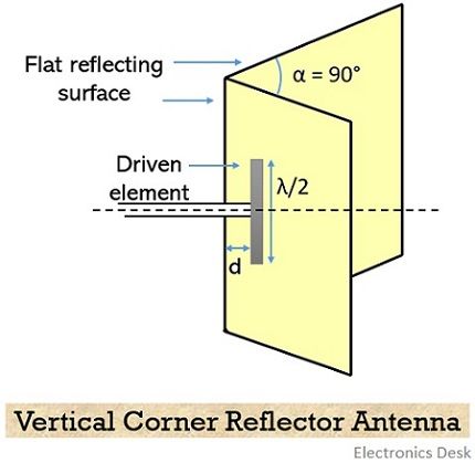
Generally, the driven element in corner reflector antennas is either a half-wave dipole or collinear dipoles and are present in parallel orientation at a certain distance from the vertex of the corner reflector.
However, the use of cylindrical or biconical dipoles, despite using thin wires is preferable here.
To have higher gain with a small value of α, the reflector is designed with increased side lengths. Also, in order to have higher efficiency with a smaller value of α, the spacing between the vertex and feed element is increased.
Radiation Pattern
The figure below represents the radiation pattern of a vertical corner reflector along the main axis: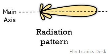
Advantages
- It offers ease of construction.
- It possesses high directivity by reflecting the electromagnetic wave in the direction of its source.
Disadvantages
- Its presence makes the antenna arrangement quite bulky.
- The use of this reflector increases the cost of the corner reflector antenna.
Applications
These majorly finds applications in radar systems, to hide the presence of defence vehicles from the enemy radar. This implies it is used for hiding due to its special feature of reflecting the signal exactly in the same direction from which it is coming when α is precisely 90° and these vehicles are constructed with less sharp corners.
These are also used in television signal reception thus finds applications in home antennas. Along with this it is also majorly used in optical communication applications.