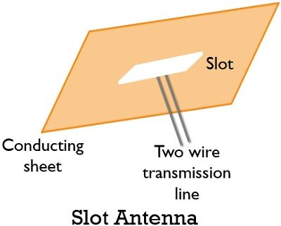
Definition: A type of antenna with an opening cut of certain dimensions in a metallic conductor which is excited using a two-wire transmission line or coaxial cable is known as a slot antenna. These antennas operate in the frequency ranging between 300 MHz to 30 GHz.
It is generally formed by making an elongated slot cut of about λ/2 length and width very less than λ/2 in a metallic conductive sheet. The excitation to the slot is provided at the centre or off the centre.
A horizontal slot antenna provides a vertically polarized signal. While a vertical slot antenna gives the horizontally polarized signal.
Operating principle
Slot antennas operate on the principle that whenever a high-frequency field is present across the slot in a metallic sheet, then energy is radiated.
This is the reason when a slot is cut from the surface of the conductive plate then on energizing the slot, the electromagnetic wave is radiated thus acts as an antenna. Due to the presence of a slot, it is named as a slot antenna.
Thus we can say a conductive surface with a slot of particular dimensions is referred as a slot antenna.
Working of Slot Antenna
Suppose we have a rectangular conductive sheet over which a horizontal slot is cut having length λ/2 and the breadth extremely less than λ/2, let it be ω.
This half wavelength slot resembles a half-wave dipole according to radiation and gain. However, the slot antenna and half-wave dipole antenna show variation according to the polarization.
The slot antenna follows Babinet’s principle.
Babinet proposed that two complementary screens generate a similar diffraction pattern. This is known as Babinet’s principle. According to this principle, the structure of the slot antenna and the half-wave dipole structure cut out from the conducting sheet are complementary to each other.
So, the region which is cut from the conducting sheet is the half-wave dipole that acts as the slot’s complementary antenna, known as a complementary dipole antenna.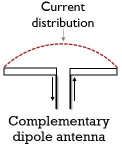
This basically shows the relatability of the radiated field and impedance of the slot to the radiated field of the dipole.
The figure below represents the slot and complementary dipole antenna: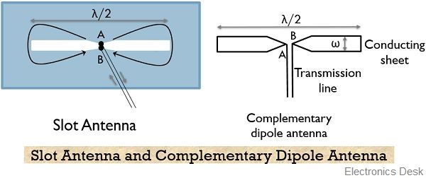
Here the external feed which is used as the excitation is provided at the center of the slot using the two-wire transmission line.
The impedance of the slot antenna relies on the feed point position. As impedance shows reduction with the shift of feed point towards the edge from the centre.
It is noteworthy here that the radiation pattern of the slot and the dipole are similar to each other. However, the electric field will be vertically polarized for the slot while horizontally polarized for the dipole.
Annular Slot Antenna
Till now we have discussed slot antenna having a rectangular slot. But it is not necessary to have a rectangular slot only, as the slot in the conducting sheet can be made in any convenient shape.
Annular slots are the slots of circular shapes that are present on the metallic sheet. The ease of construction and analysis highly facilitates making rectangular or circular slots.
A narrow beam of radiation is produced by the annular slot antenna.
Slotted Waveguide Antenna
In slotted waveguide antenna multiple slots are present in a waveguide forming a group of antennas.
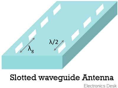
The separation between each slot is such that there exists half guide wavelength distance between center of each adjacent slot. These slots are cut on the two sides of the waveguide which is separated by the central line.
It is noteworthy here that the guide wavelength is greater than the free-space wavelength.
Impedance of the Slot Antenna
The relation between the terminal impedance of slot, Zs and dipole Zd is given as:
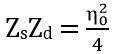
: η0 denotes the intrinsic impedance of free space.
Since, η0 = 376.7
Thus on substituting, we will get
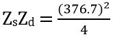
ZsZd = 35475.7225
Hence,
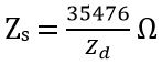
Therefore, we can determine the properties of the complementary slot antenna if the properties of the dipole antenna are known.
For a half-wave dipole antenna
Zd = 73 + j (42.5) Ω
Then the terminal impedance of slot antenna will be:
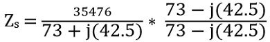
On simplifying, we will have
Zs = 363 – j (211) Ω
Applications of Slot Antenna
Arrays of slot antenna find applications in aircraft. As the metallic surface of the aircraft allows the formation of the slot directly on it. These are also used in mobile radar systems.