Definition: A type of antenna that is designed to collimate the incident divergent energy in order to convert it into plane waves using proper lens material is known as Lens Antenna. It is a microwave antenna that uses the principle of refraction utilized by the optical lens for light in order to re-radiate the received energy in the desired direction.
The operating frequency range offered by lens antenna begins at 1 GHz but is majorly used above 3 GHz. This means these are designed to be operated at very high frequency.
It is to be noted here that in case of low-frequency operations, the dimensions become very large thus antenna arrangement becomes bulky. This is the reason these are suitable for very high-frequency operations.
Content: Lens Antenna
Introduction
Lens antenna is regarded as a radiator which operates on collimated action of optical lens. Its operation is similar to reflector antennas.
In the previous article, we have discussed the reflector antenna that allows the energy falling on its surface to collimate in the desired direction. Thus, results in converting the spherical waves into plane waves.
This causes an increase in the directive gain offered by the antenna arrangement.
Similar to a parabolic reflector, a lens antenna is designed to collimate the incident energy which is diverging in nature, in the desired direction. This prevents the undesired spreading of the energy thereby improving the efficiency.
Operating Principle
Lens antennas use the principle of the converging lens in order to collimate the energy that incident on it. We are familiar with how a simple optical lens performs collimating action.
We have seen in a parabolic reflector that the energy emitted from the feed element which is present at the focus of the reflector when reaches its surface then it converts the spherically radiated microwaves into plane waves. Hence improves the directivity.
In a similar way in case of lens antenna, the point source acts as the feed that emits the microwave energy towards the surface of the optical lens. This optical surface forces the radiated spherical wavefronts to get changed into collimated one.
It is noteworthy here that in general practice the collimating lens is made of dielectric material which possesses the finite value of dielectric constant. But these can also be constructed with materials that exhibit less than unity refractive index at radio frequencies.
It somewhat displays reciprocity theorem thus is used at the transmitting as well as receiving ends.
Working of Lens Antenna
In the previous section, we have discussed the principle of operation of the lens antenna. Let us now see, how actually it is designed for transmission and reception of signals in the microwave frequency range.
- Consider that we have a converging type of optical lens present at a certain position and source from where the energy is to be released is present at the focal point at a distance of focal length along the axis of the optical lens.
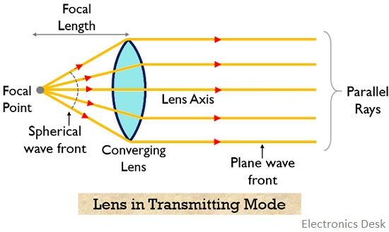
We all must be aware that from the optical point of view, light when falls on the surface of the lens then it bends due to refraction and the way of bending of light energy depends on the curvature as well as material from which the lens is made.
So, when the feed antenna (generally horn or dipole antenna) is present at the focal point (present on the left-hand side) of the lens then the spherical wavefront emerging from the source which is diverging in nature incident in the surface of lens antenna.
Thus, after incidence when the rays pass through it then the diverging rays collimate due to refraction and is converted into plane wavefronts. Hence, the parallel rays are obtained at the right-hand side of the optical lens. In this way, the signal from a lens antenna using a feed element is transmitted.
In a similar way, if this antenna is made of dielectric material, then the radio-frequency electromagnetic waves are collimated in a similar way and are transmitted further.
- It is to be noted here that, the converse of the above-discussed action of the lens antenna is also true. Consider the below-given figure:
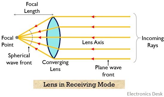
Here parallel rays that incident on the surface of the converging lens, converge on the left-hand side of the lens at the focal point due to refraction mechanism. Thus, this operation is utilized when it is used for receiving mode.
This shows that it follows the principle of reciprocity theorem.
An important point to be noted here is that to achieve better focusing properties at radio frequencies, the medium should have a refractive index less than unity. This leads to provide straight wavefronts even when the refractive index of the material is high or low.
Types of Lens Antenna
The two major classifications of lens antennas are as follows:
- Delay Lens Antenna: The type of lens antenna that causes retardation in the travelling wavefronts due to the lens media is known as delay lens antenna. These are sometimes known as a dielectric lens.
The reason behind this is that, due to the medium of the lens, the electrical path length is increased and the wave undergoes retardation.
The figure below represents the action of the dielectric lens: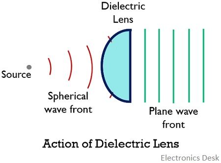
These are further classified into two categories:
- Non-metallic dielectric lens
- Metallic dielectric lens
The above classification is based on the type of dielectric material (i.e., either metallic or non-metallic) used for construction.
- Fast Lens Antenna: In this type, the travelling wavefronts are speed up by the lens media. Here, due to the medium of the lens, the electrical path length gets decreased and the wavefronts get accelerated.
It is also known as the E-plane metal plate antenna. The figure below shows the fast lens antenna: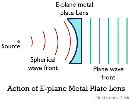
Advantages
The advantages are as follows:
- Unlike the parabolic reflector, in lens antenna, the aperture of the antenna is not obstructed by the feed point.
- It offers more flexibility in design tolerance, this means twisting in a lens antenna is possible. This is due to the reason that wave incident at one side and emerges from the other.
- It is used for very high-frequency applications.
Disadvantages
The disadvantages are stated below:
- The low-frequency use of lens antenna makes the antenna arrangement heavy and bulky.
- These antennas are more expensive than reflector antenna for the same gain and bandwidth.
Applications
These are wideband antennas that are referred as microwave antennas and are suitable for frequency above 3 GHz. The dielectric lens antennas are frequency sensitive thus this specific type is not used over the wide frequency range.