The term attitude relative to satellite communication corresponds to the orientation of satellite (vehicle) in space. Attitude control is defined as controlling the orientation of the axis of satellites that are orbiting in space. So, the complete set of devices forming a system that helps to analyze and control the orientation of satellites in space is known as an attitude control system.
The major function of attitude controlling is to facilitate pointing the satellite’s antenna accurately at our specific region of interest on the ground-based stations and solar panels in the direction towards the sun.
Content: Attitude Control System
Introduction
We have got the idea that attitude defines the orientation of a satellite (i.e., spacecraft). While attitude control is the arrangement required to maintain the satellite in the desired orientation.
Attitude controlling is a quite necessary task. Now, the question is, why attitude control is needed.
Keeping the attitude of the satellite in control is required due to the fact that the antenna on the earth-based station must be aligned accordingly to have great directionality.
To understand this, consider that there is a satellite in space that is assigned to take snaps of a specific region on the surface of the earth. So, to achieve this, the orientation of the satellite must be such that the satellite must point down towards the earth. When the satellite’s antenna will point accurately towards the earth then only the desired task of taking the snap of the required position will be fulfilled. Also, at the same time, the positioning must be maintained till the time it is needed because if it changes then the alignment will get changed and so the output.
Not only this, when we consider earth environmental satellites then it also requires attitude control because the earth sensing instruments in such systems must properly cover the regions which are required to be covered. Thus, we can say that an attitude control system is required to align and maintain proper pointing of the satellite in the right direction.
Satellite Attitude
In general, the attitude is described angle-wise rather than distance-wise. For a body-centered coordinate frame (called body frame), attitude corresponds to the angular rotation with respect to it.
The three axes defining the attitude of satellites are roll, pitch, and yaw. The figure below represents the three axes with respect to the earth.
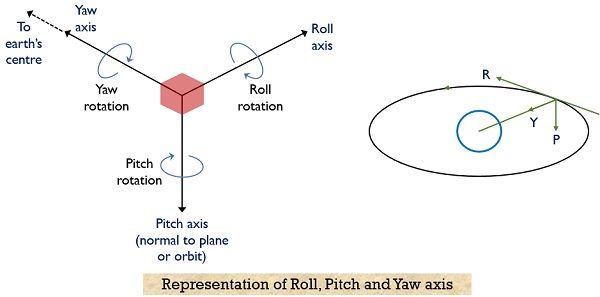
Here it is clearly shown that the axes are passing through the center of gravity. The angle formed by the roll, pitch, and yaw axes is called the roll, pitch, and yaw angle respectively. Here roll corresponds to rotation about the x-axis, the pitch is the rotation about the y-axis and yaw is the rotation relative to the z-axis.
When an equatorial orbit is considered then the satellite rotation about the roll axis causes the footprint motion north and south. Whereas when rotation is about the pitch axis then the footprint moves east and west. While the antenna footprint is rotated when the movement of the satellite is about the yaw axis.
Now, you must be thinking, how can we check whether the attitude is right or not.
So, basically, to check for the correctness of attitude we must first know actually what attitude is required. The accuracy and the rate with which the attitude is changing are crucial parameters of defining the attitude control requirements. The accuracy of the attitude corresponds to the ability of the spacecraft to properly focus the emitted radiation towards the desired target i.e., earth station on the ground. This means that even if the spacecraft undergoes a slight shift then also the beam must be centered on the target.
When the beam is emitted towards the target it makes a cone and the angular size of the cone formed is regarded as attitude accuracy denoted by ψ. So, in such a case, the control system must properly operate so that the emitted beam must be focussed towards the receiving antenna.
Other than the accuracy of the attitude, the rate with which the attitude changes is also an important factor while dealing with the requirements of attitude control. This is so because when satellite moves in space then sometimes there is a need to shift the attention amongst various points on the ground. This shift from one point of focus to another should be a rapid one. This is defined in terms of slew rate. As slew rate corresponds to the angular speed with which the spacecraft has changed its focus from one point to another on the ground.
Factors Affecting Satellite Attitude
Recently we have discussed the requirements of attitude control. One must think that, why do we need precision regarding slew rate, as fixing the satellite at the desired attitude according to the application would be an easier task. So, even this will not control the attitude requirements properly.
The reason for this is that space is regarded as quite a gigantic place and nasty as well. So, even after fixing the satellite at a specific attitude number of forces, called disturbance torques hold the ability to change the attitude unnecessarily. The reason for the generation of disturbance torques is regarded as factors that affect the satellite attitude.
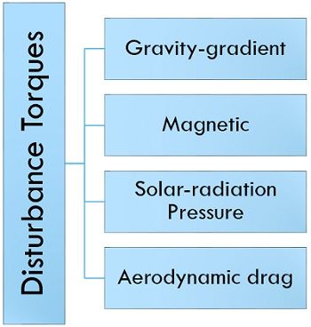
- Gravity-gradient Torque: We know that there is a gravitational field of earth that acts on the objects. Gravity gradient torque is generated when the earth exhibits different gravitational forces on different parts of the satellite orbiting in space. This is so because according to Newton, the gravitational force varies according to the square of the distance of separation.
- Magnetic Torque: This disturbance torque is the result of the magnetic field offered by the earth. We know that charged particles exist in space, and because of the existing charged particles, the surface of the satellite resultantly develops its own charge producing a different dipole, i.e., north-south.
Due to this reason, in the presence of a magnetic field the satellite which is now dipole charged will try to align itself relative to the earth’s magnetic field, just like a compass tries to do. However, the magnetic torque generated will depend on the magnetic dipole of the spacecraft and the strength of the magnetic field. - Solar-radiation pressure: Sun is another source of generation of disturbance torque as the sun exerts a small force on the satellite orbiting earth, this is known as solar radiation pressure. Now, the question arises how can the sun exert force. So, the light from the sun is nothing but photons. The photons are considered to be massless but have momentum. And when the photons strike then momentum is transferred to the surface of the satellite.
- Atmospheric drag: The satellite orbiting the low earth orbit experiences a drag force due to which it enters the atmosphere and gets burnt. However, on the different parts of the satellites, this drag force varies due to variation in the drag coefficient. This difference in drag coefficient leads to cause drag torque.
Block Diagram of Attitude Control System
Here shown the illustration of the attitude control subsystem:
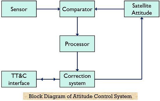
Here the sensors present are used to detect the attitude of the satellite and the output of which is given to a comparator. At the comparator, the actual satellite attitude is compared with a reference value leading to generate error signals according to which necessary corrections are made. Now, let see how to deal with errors when the difference in actual and reference attitude is obtained.
Methods for Attitude Control
The method of incorporating a horizon detector is quite crucial in exercising attitude control. In this method, infrared sensors help to detect the rim of the earth relative to space’s background. This method incorporates 4 sensors, each of which covers a quadrant making the center of the earth a reference point.
When the orientation of the spacecraft changes then this is detected by one or more sensors then the system generates restoring torque corresponding to the detected change. Though changes occur at the satellite region of space, one can send the control signals from earth-based stations according to the attitude information achieved from the satellite. Whenever attitude change is required then attitude maneuvers are implemented and the earth station sends the required control signal.
The torque that controls the attitude can be generated in the following ways:
1. Passive attitude control: This controlling action is somewhat similar to open-loop configuration, which enables the satellite to remain in the desired attitude where its position is maintained with the use of little or sometimes even no torque. This method helps in stabilizing the satellite without hampering the energy supplies of the satellite.
Examples:
- Gravity gradient stabilization
- Spin stabilization
- Dampers
2. Active attitude control: This is a closed-loop operation that needs feedback to make the desired adjustments. Unlike passive attitude control, this method does not offer the overall stabilizing torque to compensate for the disturbance torques. However, in the active controlling, in response to disturbance torques, corrective torques are produced.
Examples:
- Momentum wheels
- Magnetic torquers
- Mass expulsion devices (like gas jets and ion thrusters)
This is all about an attitude control system.