Convolutional code is another type of error-correcting code where the output bits are obtained by performing a desired logical operation on a present bitstream along with considering some bits of the previous stream. This coding technique rather than depending on the block of bits shows dependency on bitstream.
It is also a linear code that consists of the shift register, used for temporarily storing the bits, shifting operation of bits along with X-OR logic circuits to give rise to an output code.
This was proposed by Elias in 1955 and further, in 1973, Viterbi introduced an algorithm for decoding it which was named the Viterbi scheme.
Content: Convolutional Code
- Error-Correcting Codes
- Introduction to Convolutional Code
- Block Diagram
- Example
- State Diagram Representation
- Trellis Diagram
What are Error-Correcting Codes?
Error-correcting codes are the way to deal with the errors introduced in the actual message signal at the time of transmission in data communication. It is regarded as error detection and correction technique by which the information signal is encoded using redundant bits. These are categorized as:
- Block Code
- Convolutional Code
This content is subjected to convolutional coding.
Introduction to Convolutional Code
Convolutional coding is known to be one of the most frequently used error correction techniques relative to digital wireless communication.
Previously, we have discussed block codes where the data stream is divided into blocks of bits having a specific length and is encoded using parity bits. However, block code and convolutional code are different from each other as the two are based on different encoding principles.
While discussing block codes, we have seen that there is a linear combination of information bits with parity bits in multiple blocks that are decoded by the receiver.
However, the major difference which is noticed in convolutional code is that, unlike block code, in convolutional code, only the parity bits with possible errors are received by the receiver. The receiver decodes to have the best possible bit sequence (which is nothing other than the message bits) from the obtained bitstream.
This seems quite confusing but it is interesting. We will understand the approach followed by considering an example later.
For convolutional code, it is said that the message has data streams of arbitrary length which undergoes encoding into a sequence of bits by the application of a Boolean function to the data stream.
Block Diagram for Convolutional Code
The major elements of the convolutional coding technique include the shift register that acts as temporary storage and whose stored bits undergo shifting using a sliding window, a logic circuit that performs modulo-2 addition incorporating X-OR function. Before discussing the approach used in convolutional coding let us understand some important parameters.
Basically, there are mainly two parameters that define the convolutional coding which are as follows:
- Constraint length: The constraint length corresponds to the length of the convolutional encoder i.e., the overall window size in bits, within the shift register. It is denoted by K (uppercase). Sometimes also denoted by L as it might cause confusion with k (lowercase). There is another parameter ‘m’ which corresponds to the number of input bits retained within the shift register once it is entered in the encoder.
- Code rate: Code rate is the ratio of a number of bits shifted at once within the shift register (denoted by k) to the total number of bits in an encoded (generated) bitstream (denoted by n). Thus, it is given as:

The figure below represents the block diagram showing the convolutional coding technique:
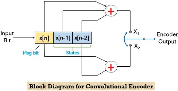
Basically, x[n-i] is the encoding state. Here we have shown two blocks x[n-1] and x[n-2], denoting there are 2 states of the encoder which is nothing but the previous bits. Input bit x[n] is fed to the encoder in order to obtain the parity bits.
Now, the question arises – how parity bits (i.e., the output bits) are calculated?
So, the parity bits are calculated using the states of the encoder and the input bit. In the above-given block diagram, we have considered 2 states with a single input bit. Thus, the overall constraint length i.e., K will be 3. Thus, for the convolutional code, it is said that the output stream shows dependency on previously-stored bits in memory along with the present input bits.
It is to be noted here that as the obtained output contains the parity bits thus, it will be wrong to assume that a longer constraint length will offer faster decoding. This is so because even a longer constraint will hold parity bits and a large number of parity bits will not make the decoding process quick.
Example for Convolutional Code
To understand how convolutional encoding takes place. Consider the convolutional encoder shown below:
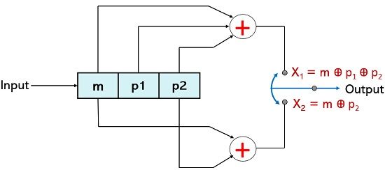
Here, there are 2 states p1 and p2, and input bit (i.e., k) is represented by m. The two outputs of the encoder are X1 and X2 which are obtained by using the X-OR logic function. Thus, for the above configuration,
X1 = m Ꚛ p1 Ꚛ p2
X2 = m Ꚛ p2
Now, as we can see that there are 2 states thus, the various combinations of the two states can be represented as:
| p1 | p2 | State |
|---|---|---|
| 0 | 0 | Sa |
| 0 | 1 | Sb |
| 1 | 0 | Sc |
| 1 | 1 | Sd |
It can be clearly analyzed that here input bit k = 1, the encoded output bits n = 2, and the constraint length K = 3. So, in such case the code dimension (n,k) = (2,1). Hence code rate will be 1/2.
There will be a positional switching between X1 and X2, thus the overall output will be in a manner:
X = X1.X2.X1.X2 —-
Let us now tabulate the encoder operation by considering the current state (CS) and the next state (NS).
| m | p1 | p2 | X1 | X2 | CS | NS |
|---|---|---|---|---|---|---|
| 0 | 0 | 0 | 0 | 0 | Sa | Sa |
| 1 | 0 | 0 | 1 | 1 | Sa | Sc |
| 0 | 0 | 1 | 1 | 1 | Sb | Sa |
| 1 | 0 | 1 | 0 | 0 | Sb | Sc |
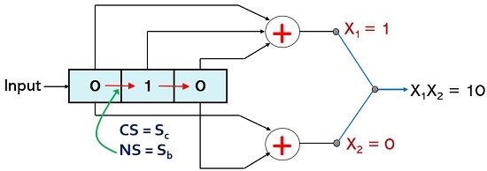
| 0 | 1 | 0 | 1 | 0 | Sc | Sb |
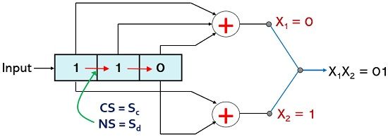
| 1 | 1 | 0 | 0 | 1 | Sc | Sd |
| 0 | 1 | 1 | 0 | 1 | Sd | Sb |
| 1 | 1 | 1 | 1 | 0 | Sd | Sd |
First, consider the various combinations of two given states p1 and p2 for bits 0 and 1 in order to understand the operation. We have considered 8 combinations over here so that we can see the operation with binary input 0 and 1 individually.
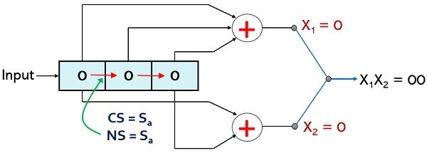
Initially, all three bits within the register are set at 0 if message bit 0 is inserted then the current state will be Sa. Also, the X-OR logic operation will result in X1 and X2 as 0 and 0 respectively. When any other message bit is inserted then earlier values of m and p1 bits will undergo the right shift but as the state combination is still 0 and 0 and so, the next state will be Sa.
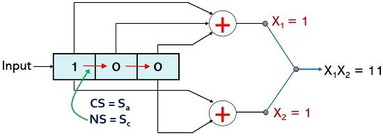
Now, if p1 = 0; p2 = 0 and input i.e., m is 1, in this case, the current state will be Sa and the values of X1 and X2 will be 1 and 1 respectively. However, when a next bit is inserted for input then all the 3 earlier bits will undergo the right shift and this will result in a new state combination as 10 therefore, the next state as Sc.
For p1 = 0; p2 = 1, and m = 0 the current state is Sb and resultantly the value of X1 and X2 will be 1 and 1 respectively. But when any other message bit will be provided as input then due to the right shift in present bits the new state combination will be 00 hence the next state will become Sa.

For p1 = 0; p2 = 1, and m = 1 the current state will Sb this will provide the value of X1 and X2 as 0 and 0 respectively. However, when another message bit will be inserted then due to the right shift within the encoder, the next state will become Sc.

For p1 = 1; p2 = 0, the current state will be Sc and if the message bit is 0 then the X1 and X2 will be 1 and 0 respectively. But when another input bit is inserted then the right shift in the present bits causes the next state to become Sb.
For p1 = 1; p2 = 0, the current state due to a combination of 1 and 0 will be Sc and for present message bit m =1, the values of X1 and X2 will be 0 and 1 respectively. However, whenever there will be another bit present at the input then the right shift within the encoder will result in the next state as Sd.
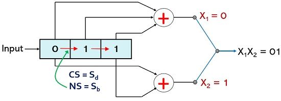
For p1 = 1; p2 = 1, the current state will be Sd and if the message bit is 0 then X-OR logic will provide X1 and X2 as 0 and 1 respectively. Whenever any next bit is required to be inserted then the right shift will cause the next state combination to be 0 and 1 thus next state will be Sb.
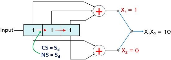
For p1 = 1; p2 = 1, the current state is Sd and for message bit 1 the logical function will give X1 and X2 as 1 and 0 respectively. As another input bit is required to be inserted then this will cause a right shift and the bit combination for the next state will be 1 and 1 and so the next state here will be Sd.
Thus, an input sequence of (01010101) produces an output sequence (0011110010010110).
State Diagram Representation for Encoder
The state diagram representation of the above-described convolutional encoder is shown below:
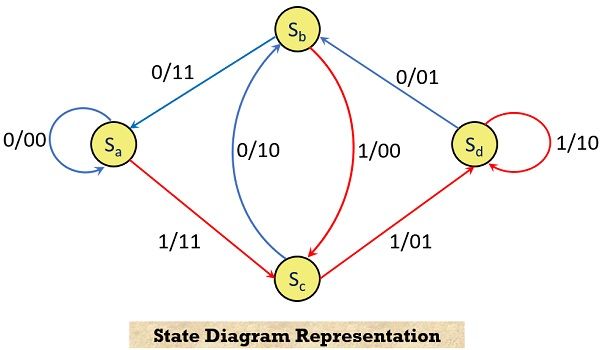
This state diagram shows the transition from one state to another of the encoder according to the input bit. In the above figure, the input bits 0 and 1 are represented by blue and red lines, respectively.
All the 4 states Sa to Sd are considered here. The path information from one state to another is given in the fashion input/output. This can be understood in a way that a path from state Sa to Sa is obtained for input/output as 0/00. Similarly, the path from state Sa to Sc corresponds to input/output as 1/11. Likewise, the path from state Sb to Sa shows an input/output relation of 0/11.
Trellis Diagram for Decoder
The trellis diagram is obtained by the state diagram representation which is shown above. By using a trellis diagram one can efficiently decode the obtained code sequence.
Here we have marked the four current states and next states, in the two columns. Each state of the current state column forms connections with 2 other states of the next state column according to the path in the state diagram representation.
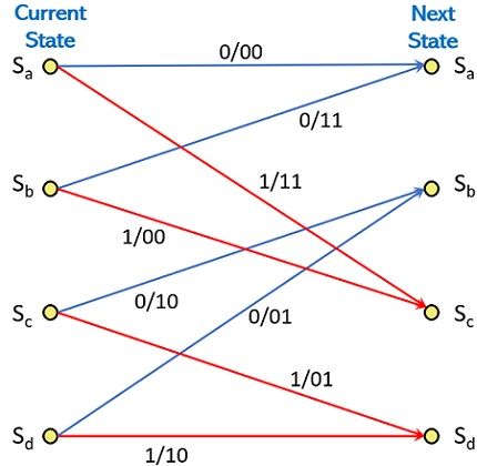
For input 0 the CS and NS both are Sa resulting in output 00. Likewise, when input is 1, then CS and NS are Sa and Sc respectively. This combination provides output 11. In a similar way, when input is 0, CS and NS will be Sb and Sa respectively, with the current state combinational output as 11.
Basically, for decoding operation, the decoder needs to determine the sequence of stream which actually generates the parity bit sequence which is received at the receiver. This is achieved by observing the best path through the trellis that provides the sequence of parity bits received.