Both LVDT and RVDT are basically sensors that are used to measure displacement. But the major difference between LVDT and RVDT is that an LVDT senses and transforms linear displacement into an electrical signal. While an RVDT senses angular displacement and transforms it into an electrical signal.
Some more crucial differences exist between LVDT and RVDT that we will discuss in the upcoming section. But before moving towards that just put a look at the contents that we are going to discuss in this article.
Content: LVDT Vs RVDT
Comparison Chart
| Parameter | LVDT | RVDT |
|---|---|---|
| Senses | Linear displacement | Angular displacement |
| Full Form | Linear Variable Differential Transformer | Rotatory Variable Differential Transformer |
| Core shape | Rectangular shaped | Cam shaped |
| Measurement range | Lies between +/- 100 micrometer to +/- 25 cm. | Ranges between = 40 to -40 degrees. |
| Sensitivity | 2.4 mV/ volt/ degree of rotation | 2 to 3 mV/ volt/ degree of rotation |
| Applied input voltage | 1 V to 24 V rms. | 3 V rms. |
| Frequency range | 50 Hz to 20 KHz. | 400 Hz to 20 KHz. |
| Applications | In measuring systems like weight an pressure etc. and in inspection of products. | In controlling systems like fire controlling and antenna and radar systems. |
Definition of LVDT
LVDT is an acronym used for the linear variable differential transformer. It is a transducer that has the ability to change linear displacement into an electrical signal.
Basically, according to the displacement generated by the core, the voltage generated by the transducer shows variation. Thereby showing liner change in the produced electrical signal.
The figure below represents the circuit of an LVDT:
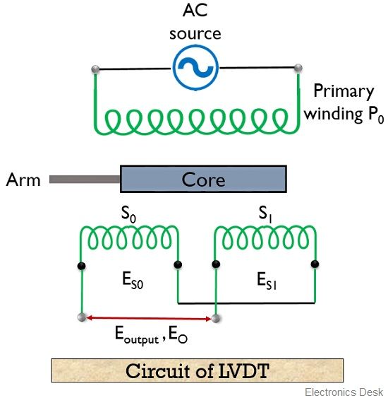
As we can see that a Linear variable differential transformer is composed of a primary winding P0 along with 2 secondary windings S0 and S1.
The ac supply is provided to the primary winding of the transformer while the two secondary windings are kept equidistant on both the sides of the primary winding. A rectangular core is placed in the structure, which is moved linearly within the former.
The movement of the core in different directions produces a differential voltage at the output.
Now a question comes in our mind that how only due to movement of the core, a voltage is generated?
So let us see the reason behind it.
Basically, the produced differential output does not solely depend on the movement of the core but also on the applied ac voltage at the primary winding of the transformer.
Because due to the applied ac signal, an alternating magnetic field is generated. Due to this magnetic field, an ac voltage gets induced in the two secondary windings. But the variation in the induced voltage generates 3 different cases.
Will we consider 3 different cases in order to understand the operation of an LVDT;
Firstly, when the core is present at the initial or normal position. Then the voltage induced in both the secondary windings S0 and S1 will be equal.
As the two windings are serially joined. Thus the differential voltage at the output will be 0.
Secondly, when the core is moved to the left of the normal position, then, in this case, the linking flux in S0 will be more than that of S1. So, the voltage at S0 will be greater than S1.
So, the differential output voltage is given as
E0 = ES0 – ES1
Thirdly, when the core is moved to the right side form the central position, then this time the linking flux in S1 will be more than S0. So the voltage produced as S0 will be less.
Then the differential output voltage will be
E0 = ES1 – ES0
Thus we can say that change in output voltage in case of LVDT is proportional to the displacement of the core.
Definition of RVDT
RVDT is an abbreviation used for the rotatory variable differential transformer. It is a transducer that has the ability to sense angular displacement and converts this displacement into an electrical signal.
Generally, the operation of RVDT is somewhat similar to an LVDT. However, in the case of RVDT, a cam-shaped core is taken that is allowed to be rotated between the windings of the transformer with the help of a shaft.
The figure below shows the circuit of the RVDT:
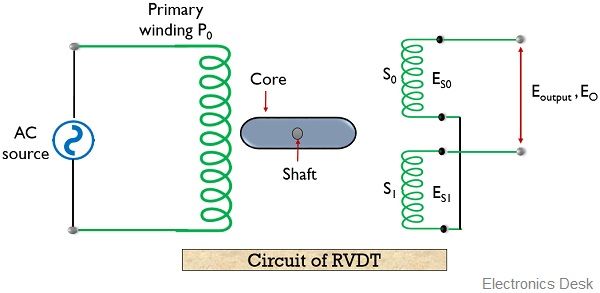
Here we can clearly see, that the core is placed between the primary and two secondary windings of the transformer.
The external supply is provided at the primary winding of the transformer and the differential output is taken from the two secondary windings.
As we have already mentioned that the operation of RVDT is similar to LVDT. Thus here also the externally supplied ac source and rotation of the core generates a differential voltage at the output.
Here, also we will consider 3 conditions in order to understand the operation performed by the RVDT.
Firstly, when the core is at the centrally placed or at the null position. Then due to the externally supplied ac voltage, a magnetic field gets generated and this magnetic field induces an equal voltage at both the windings.
So, this resultantly causes the differential voltage to be 0. As here ES0 will be equal to ES1.
Secondly when the core is rotated in a clockwise direction then, the greater part of the core will come across the secondary winding S0. This will cause more flux linkage across S0 rather than S1.
Therefore, the differential voltage at the output will be
E0 = ES0 – ES1
Likewise, in the third case when the core is rotated in an anti-clockwise direction then, the greater portion of the core will be present at the secondary winding S1. Thus more flux will link across S1 than S0.
Hence, now the differential output voltage will be
E0 = ES1 – ES0
So, we can say the more the angular displacement will be the greater will be the differential output.
Key Differences Between LVDT and RVDT
- LVDT stands for the linear variable differential transformer. Whereas, RVDT is an acronym used for the rotatory variable differential transformer.
- The measuring range of LVDT lies somewhat between ± 100 μm to ± 25 cm. While the measuring range of RVDT is nearly ± 40 degrees.
- As LVDTs are linear devices, thus their sensitivity is somewhat 2.4mV/ Volt/ degree of rotation. As against the sensitivity of RVDT lies between 2 to 3 mV/ Volt/ degree of rotation.
- The core shape in case of LVDT is rectangular while that of RVDT is cam shaped.
- The applied input voltage at the primary winding is around 1 to 24 V rms. However, it is very low in case of RVDT and its value is nearly about 3V.
- The operating frequency range of LVDT is 50 Hz to 20 KHz, whereas that of RVDT is 400 Hz to 20 KHz.
- LVDTs majorly finds its applications in measuring force, weight, pressure etc. and also used in product inspection as well as testing the strength of the soil. However, RVDTs are used in various controlling systems like fire and vehicular control. In turbine operation and antenna & radar systems.
Conclusion
So, from the above discussion, we can conclude that in the case of both LVDT and RVDT the response produced is linear. But one relies on linear displacement while the other on angular displacement.