Definition: Hartley oscillator is a type of LC oscillator that generates undamped sinusoidal oscillations whose tank circuit consists of 2 inductors and a capacitor. In the tank circuit, the two inductive coils are serially connected together forming a parallel combination with the capacitor.
Hartley Oscillator was invented by Ralph Hartley in 1915 and hence named so.
In normal LC oscillator, the amplitude of the oscillations generated by the circuit is uncontrollable. Along with that tuning to a particular frequency is quite difficult.
So unlike normal LC oscillator, the Hartley oscillator uses an LC parallel feedback configuration that has self-tuning base oscillator circuit.
Content: Hartley Oscillator
Working Principle and Circuit Diagram of Hartley Oscillator
The figure below represents the circuit diagram of Hartley oscillator:
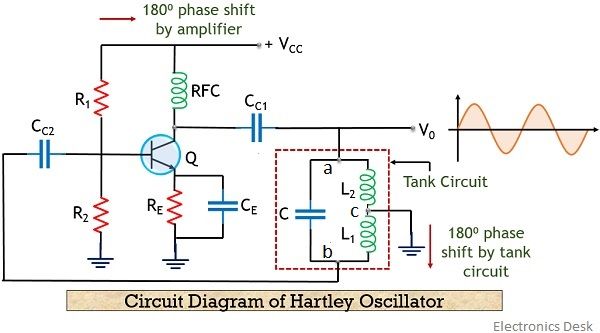
Here, in the above figure, we can clearly see that various circuit elements are present. Let us first understand the use of these elements in the circuit.
The required biasing o the circuit is provided by resistors R1, R2 and RE. While CC1 and CC2 are the coupling capacitors.
An RFC is present in the circuit, which is used to abbreviate radio frequency choke coil. In high-frequency applications, the reactance of RFC becomes very large. Thus can be considered as open-circuited.
While RFC exhibits almost zero reactance in DC condition, hence do not cause any issue for DC capacitors.
Therefore, isolatedly maintains ac and dc conditions in the circuit.
Also, a phase shift of 180⁰ is provided by the transistor amplifier present in the circuit. The oscillating frequency relies on the components of tank circuit L1, L2 and C.
So when dc supply voltage Vcc is provided to the circuit, then with the increase in the collector current of the transistor, the capacitor in the tank circuit starts charging. We are already aware of the fact that capacitor stores charge in the form of the electric field.
So, the capacitor continues its charging until it gets fully charged. But once it gets fully charged then the capacitor begins to discharge through inductor L1 and L2.
This discharging of the capacitor results in charging of the inductor. And we know inductor stores the charge in the form of the magnetic field. So, the complete discharging of the capacitor will automatically cause the charging of the inductor and vice-versa.
This continuous charging and discharging will provide sinusoidal oscillations at the output. However, it is noteworthy here that these oscillations are damped oscillations, as amplitude is decreasing continuously.
This decrease in amplitude is the result of internal resistance of inductor that causes heat loss in the circuit and is denoted by I2R.
It is to be noted here that between point a and b in the circuit, a phase shift of 180⁰ is provided by the tank circuit.
As here point c is grounded. Thus for a particular time instant when a is positive then b will be negative wrt c and vice-versa. Therefore, the tank circuit provides a phase shift of 180⁰.
As we have already discussed that the tank circuit generates damped sinusoidal oscillations. Thus it is required to be amplified otherwise the oscillations will die out after a certain point of time.
So, to overcome this problem, the output of the tank circuit is provided as input to the common emitter configuration transistor. The sinusoidal signal when provided to the transistor, gets amplified. The feedback energy is taken by the mutual inductance between inductive coils L1 and L2.
The amplified output from the transistors then provides the charging energy to the capacitor in the tank circuit to produce further sinusoidal oscillations.
This amplified output compensates for the losses generated by the tank circuit. Thus the tank circuit provides continuous sinusoidal oscillations of constant amplitude at the output.
In this way, a tank circuit works.
Frequency of Oscillations in Hartley Oscillator
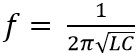
The frequency of oscillations of the sinusoidal signal generated by the tank circuit is given as
But in Hartley oscillator, we consider 2 inductors in the tank circuit thus equivalent inductance will be given as
Leq = L1 + L2
The mutual inductance between the coils must also be taken into consideration while calculating the equivalent inductance, so
Leq = L1 + L2 + 2M
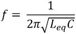
Thus the oscillating frequency is given as
Advantages of Hartley Oscillator
- It provides sinusoidal oscillations of constant amplitude.
- The oscillating frequency can be changed by the use of a variable capacitor.
- The circuit is not complex.
- Practically a single tapped coil can also be used in place of 2 inductors in the circuit.
Disadvantages of Hartley Oscillator
- Due to the presence of harmonics, sometimes distorted sinusoidal oscillations are generated.
- It does not find use in low-frequency applications.
Applications of Hartley Oscillator
Hartley oscillators widely used in the generation of sinusoidal waveforms of a certain frequency. Thus these are suitable for radio-frequency applications, thus find their use in radio receivers.