Definition: A Reflex Klystron is a specialized low-power vacuum tube used to produce oscillations at microwave frequency. Its principle of operation is velocity and current modulation.
Klystrons are basically specialized tubes used as amplifiers and oscillators at the microwave frequency range.
Content: Reflex Klystron
Need of Reflex Klystron
We have already discussed Two-cavity Klystron and Travelling Wave Tube in our previous articles. We know a two-cavity klystron acts as an amplifier to provide amplification of RF signals.
So, can that same structure be utilized for generating oscillations?
Basically, a two-cavity klystron can be converted into an oscillator, but some disadvantages are associated with it. As we know to design an oscillator, positive feedback must be provided to the input in a way to have a magnitude of loop gain as unity.
So, if we design a klystron oscillator using a two-cavity klystron then to have a change in oscillating frequency, the resonant frequency of the two-cavities is also required to be changed. Thereby leading to cause difficulty in generating oscillations. Thus to overcome the disadvantage, a reflex klystron having a single cavity was invented to have sustained oscillations at microwave frequency.
Operating Principle
Like a two-cavity klystron, a reflex klystron utilizes the phenomenon of velocity and current modulation to produce oscillations. However, there exist variation in constructional structure and the respective applications of the two. A reflex klystron consists of a single cavity that performs the action of both buncher and catcher cavity. As to have oscillations, feedback is needed to be applied at the input which is provided by the oscillator.
While moving electrons undergoes velocity modulation and the repeller applies repulsive forces on them. This leads to the formation of a bunch of electrons. Further, this bunching will lead to cause, current modulation.
We will discuss the working of a reflex klystron in detail but before that let us see how it is constructed.
Construction of Reflex Klystron
The basic schematic of a reflex klystron is shown below:
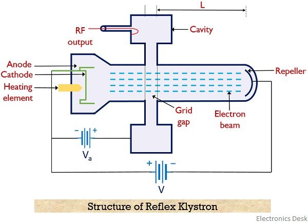
The structure consists of a cathode and focusing anode that combinedly acts as an electron gun for the tube. The cathode emits the electron beam which is focussed inside the tube by the focusing anode. Also, a positive potential is provided as input which sets up an electric field inside the cavity.
- As it is a single cavity structure, thus single cavity act as buncher and catcher cavity separately. At the time of forward movement of the electron beam, it acts as a buncher cavity. While at the time of backward movement, it is a catcher cavity.
A repeller plate that causes backward movement of the electron beam is present at the opposite end of the electron gun. The potential at the repeller is made extremely negative in order to permit repulsion of like charges.
- Repulsion is necessary in order to build electrical oscillations, as output power must be fed to the input. So the velocity modulated electrons must have to travel a backward path in order to provide feedback. Thus repeller is used in the structure of the klystron.
Working of Reflex Klystron
As we have already discussed the fundamental principle of operation of a reflex klystron is velocity and current modulation. So, consider the above figure.
- Initially when the electron beam is emitted by the electron gun, then the early electrons, ee experience a very high potential. Due to this, a strong electric field gets generated inside the cavity gap, leading to cause movement of electrons towards the repeller with a very high velocity.
Due to high velocity, the electrons penetrate deeper into the region of the repeller and thus require greater time to repel back towards the catcher cavity. - But when the externally applied potential is almost 0, then the electron moves with a uniform velocity with which it was emitted by the gun. These electrons are generally known as reference electrons er.
So, in this case, er will not penetrate deeply into the repeller surface and gets repelled by the repeller in a lesser time than the early electron. - Further, the electron that is emitted by the gun after the reference electron experiences a highly negative potential at the cavity. This electron is generally known as late electron el and moves with a very low velocity inside the tube.
The penetration level of the late electron into the repeller space is least thus takes a minimal amount of time to get repelled back.
It is to be noted that due to deep penetration in the repeller region, ee will take more time than er while returning towards the catcher. This change in the velocity of moving electrons is known as velocity modulation. And due to this velocity modulation, all the electrons get bunched while returning towards the catcher cavity.
So, in this way bunch of electrons reaches the catcher cavity. This bunching of electrons leads to cause, current modulation inside the tube. Therefore, at the time of returning, the bunched electrons transfer the maximal of their energy to the catcher cavity. Thereby leading to cause oscillations inside the tube.
- Transit Time: Transit time is defined as the time taken by the electrons to return to the cavity gap after getting repelled by the repeller. For sustained oscillations to take place, transit time is the most important factor. Basically, the optimum time for leaving the gun is centered around the reference electron, which is considered at a 180º phase difference from the sinusoidal applied potential across the gap.
- Bunching Process: The figure below shows the process of bunching on the return journey of all the 3 categories of electrons i.e., ee, er, and el:
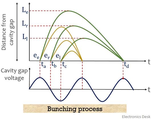
Here the x-axis represents the time and the y-axis shows the distance traveled by the electrons inside the tube.
As we have already discussed that bunching takes place at the time of the return journey of electrons. Thus it is represented in the figure that though ee, er and el, are approaching the repeller with different velocities, yet while returning all of them are bunched at a respective time.
Specifications
- The operating frequency range generally offered is 1 to 20 GHz.
- It delivers output power in the range of 10mW to 2.5 W.
- The tuning range of klystron lies between 5 GHz at 2W to 30 GHz at 10 mW.
- Theoretically, the efficiency is considered 22.78% while practically the achieved efficiency is only 10 to 20%.
Applications
As reflex klystrons are oscillators thus find applications in local oscillators receivers, radar receivers, radio receivers. Also utilized as signal sources in microwave generators and pump oscillators of parametric amplifiers.
Thank you very much.
The content provided is very good.
A very good presentation – thanks!
It is very attractive! Thank you a lot!!!