A type of satellite service that allows direct transmission of signals from the satellites present in the geostationary orbit to the personal dish antennas present in homes audiences is known as Direct Broadcast Satellite. It is abbreviated as DBS.
More simply, DBS is regarded as a technique of transmitting messages or signals directly to the general public (existing as an individual or a community) using artificial satellites orbiting the earth. The frequency band in which the DBS operates change according to the region in which the operation is taking place.
Content: Direct Broadcast Satellite
Introduction
Direct Broadcast Television is nothing but digital TV. The use of satellites for the purpose of providing services directly to homes using satellites has evolved several years ago, more specifically, DBS-TV was introduced in the year 1986. The various broadcasting services offered by the DBS are audio, video and internet services.
We have already discussed in the beginning that the frequency band of operation for the direct broadcast television service changes according to the region of operation. Generally, Ku-band (14/12 GHz) is specified for DBS services as it is less prone to problems such as interference.
The reason is that at such high-frequency bands the chances of congestion are quite low, along with that, ku-band is not utilized in terrestrial microwave communication. When the frequency is high then the receiving antenna required will also be of small length and due to smaller antenna size higher value of EIRP is obtained from the satellite. This resultantly reduces the overall cost of the equipment.
For DBS, it is said that the satellites used for providing the service offers broadcast transmission in a way that the antenna footprints are made wide so that it can cover a sufficiently large region. Thus, the satellite in motion in space when receives a signal from one earth station then that respective signal can be received by various home TV dish antennas that are present within the footprint region. Thus, DBS allows direct reception of signal that is coming from the satellite.
It is to be noted here that at the receiving end, it can be a single user that is willing to receive or it can be a group of users among which the received signal is distributed.
DBS is known to be an active field of satellite development and can help in providing innovations in other fields as well such as HDTV.
DBS – Home Receiver
The home receiver system of a Direct Broadcast System mainly has 2 units namely, an outdoor unit and an indoor unit. Let us first see:
The Outdoor Unit
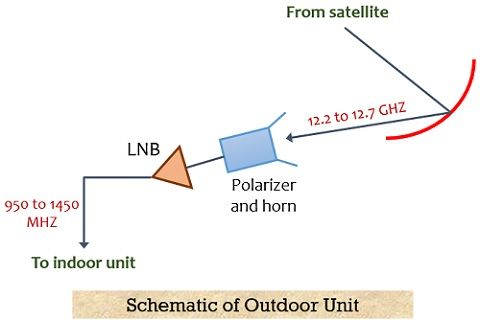
The figure below represents the schematic of the Outdoor Unit for the DBS Home Receiver:
It is clearly shown in the above figure that the dish antenna at the receiver first receives the downlink signal from the satellite which is in the range from 12.2 GHz to 12.7 GHz. The received signal is then focussed towards the receive horn. The receive horn directs the signal towards the polarizer that helps to pass the left-hand circular or right-hand circular polarized signals by performing adequate switching.
There is a low noise block that contains a combination of a Low Noise Amplifier (LNA) and a downconverter. The LNA is the unit that is responsible for the amplification of low strength signals. These are the signals that are hardly recognized by the antenna and necessary amplification must be performed without the addition of noise. Now, the downconverter comes into action and down-conversion of the signal in the range from 12.2 to 12.7 GHz is performed which is converted into the range 950 to 1450 MHz. The reason for this down conversion is that for the transmission of a signal from the connecting cable to the indoor unit, these down-converted frequencies are suited properly.
It is to be noted here that in order to gather most of the signal the arrangement of the receiving antenna must be such that it should exhibit an obstruction-free view from the satellite cluster in space. And as there is a cluster of satellites thus, the beamwidth of the antenna should be sufficiently wide so that it can receive from all the satellites present in the cluster.
Now, let us proceed towards:
The Indoor Unit
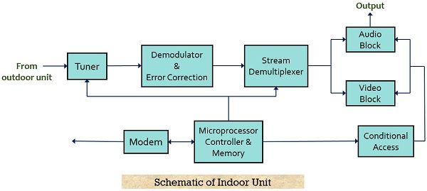
The figure below shows the block diagram representation of the indoor unit:
The tuner is the foremost block of the indoor unit which is used for selecting the transponder. As we know that the down-converted frequency is in the range from 950 to 1450 MHz but the guard band of 24 MHz is maintained by the transponder in the selected bandwidth. Thus, out of the 32 transponders, any of them must be received by the indoor unit.
It is to be noted here that for a single polarization only a signal from 16 transponders must be available. The modulation of the carrier at the centre frequency performed here is QPSK. Further, demodulation of the quadrature phase-shift keying modulated signal is performed and it is converted into the equivalent bitstream. Once this is done then an error correction scheme is implemented to eliminate the errors from the received sequence.
Here demultiplexing of the received sequence is performed where individual programs get separated and then get separated in the buffer memories so that further processing may take place. At this stage, further processing may correspond to the conditional accessibility, usage history view, modem connection, etc.
Applications of DBS
The approach of transmitting the signals directly from the satellite to the home receivers helps in providing broadcast services of audio and video along with other interactive data services. A properly installed DBS system helps in providing information when any rapid disaster (such as forest fire) occurs in any remote area.
DBS also finds applications in fields where on-demand information is required such as weather forecasting. One of the basic applications includes providing distance learning programs.