Satellite Uplink or uplink of satellite circuit is the link where the earth station is transmitting the radio wave towards the satellite which acts as the receiving station. It includes all those factors responsible for transmitting signals from an earth station to a satellite.
Satellite links allow us to enable communication over large distances.
The operation can be understood as Uplink denotes a link, up from earth station to satellite. When uplink is taking place then such satellite communication is referred to as Upload.
Content: Satellite Uplink
Introduction
We know the basics of satellite communication that signals from the ground station present on the surface of the earth is transmitted towards the satellite. Further, the satellite retransmits the signal towards the earth stations present on the various locations on the ground according to the respective application.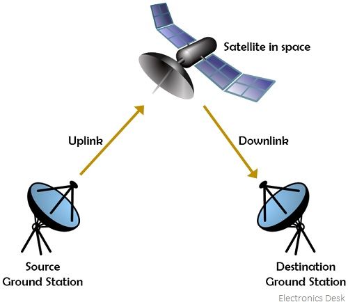
So, uplink denotes the transmission of radio waves from an earth station to satellite and downlink corresponds to the transmission from satellite to earth station. The frequency of the signal which is transmitted from the earth station to the satellite is known as the uplink frequency while the frequency of the signal transmitted from the satellite to the ground is called the downlink frequency.
The frequency selection in satellite communication is a crucial aspect. A noteworthy point over here is that the uplink frequency should always be more than the downlink frequency.
The three factors for frequency selection are as follows:
- The Low-frequency signal undergoes easy power amplification than the high-frequency signal.
- The uplink and downlink frequency should not be the same. This is so because if this happens then an amplified form of uplink signal (i.e., downlink signal) will cause jamming of the weak uplink signal, due to the close presence of uplink and downlink antenna in the satellite. This resultantly makes the amplifier unstable.
- In order to make sure that the downlink signal does not enter the receiver pre-amplifier of the satellite, filters are required to be placed. Generally, waveguides are used for signal propagation through satellites. The reason for choosing waveguides at microwave frequencies is that waveguides act as high pass filters, so when designed with proper cut-off frequency then it simply passes uplink frequency rejecting the downlink frequency (which is of no use here).
Uplink Design
The design of the Uplink is quite easy. Here the noise at the satellite receiver is not considered and transmitters of large physical size can be placed at the earth station. When we consider very small aperture terminals (VSAT) at the earth station, that is EIRP limited then here the optimization of the uplink carrier to noise power is to be carefully done.
The noise temperature of the satellite antenna which is associated with the temperature of hot earth, nearly about 300 K, limits the minimum value of noise temperature of the satellite receiver. Once the gain of the satellite antenna is increased then the G/T of the receiver will be automatically improved but this causes a reduction in bandwidth.
A noteworthy point over here is when we transmit a signal of significantly high power from the ground then the low sensitivity of the satellite receiver can be easily compensated by it.
How does a satellite uplink work?
We have already discussed that satellite uplink is the signal transmission from the earth station up towards the satellite. Here in this section, we will see how the transmission of a signal from the earth station to satellite takes place.
The figure below shows the illustration of the elements involved in satellite uplink: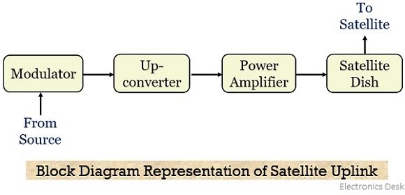
Initially, a modulator is present which is connected to the source unit via a serial cable (coaxial cable). So, the digital data coming from the source is provided to the modulator through that serial cable. The modulator converts the digital data into a modulated signal whose frequency usually is in L-band i.e., lies between 70 to 140 MHz.
This modulated signal is further provided to the upconverter that changes the radio wave, L band frequency into the microwave, i.e., C, S, X, Ka, and Ku band frequency. This range is generally above 1000 MHz. The upconverter does so by mixing the intermediate frequency with the high-frequency signal so as the get the final frequency signal.
Once the microwave frequency signal is achieved at the output of the upconverter then with the use of a power amplifier, like klystron or TWTA, the signal amplification is done after noise removal in order to raise the total effective output power. Lastly, the feed releases the signal and the dish focuses it in the direction of the satellite. Hence, by the use of a dish, the feed horn sends the signal to the satellite.
In this way, the signal from the earth station is relayed to the satellite.
Equation for [C/N0] of Satellite Uplink
In our previous content on satellite link budget we have discussed that the equation for the carrier to noise power density is given as:![]()
To consider the condition of uplink, subscript U must be added to the above equation. Thus we will get,![]()
: [EIRP]U is of an earth station,
[LOSSES]U corresponds to satellite receiver feeder losses and
[G/T]U is for the satellite receiver.
The frequency-dependent losses such as free-space loss and other losses should be calculated for uplink frequency.
So, with these considerable factors, the carrier to noise power density ratio expressed in the above equation will be the one achieved at the satellite receiver. However, sometimes at the satellite receiver, the appearing flux density is considered rather than the EIRP of the earth station.
Saturation Flux Density
It is defined as the flux density needed for the saturation of TWTA at the receiving end. It is a specific quantity of link budget calculation and its known values help to calculate EIRP at the earth station.
Consider, the equation given below, showing the relationship between EIRP and flux density.![]()
In decibels, we can write the above equation as:![]()
But FSL in decibels is given as: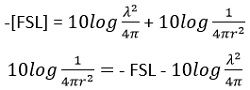
On putting the above value in the equation of flux density,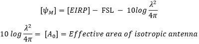
Rewriting the equation of flux density, with substituting the above equations, we will get,![]()
Thus, [EIRP] will be given as:![]()
The above equation signifies, that only spreading loss i.e., FSL is present while transmission. But, we know that there exist some other losses, thus:![]()
Thus, we can write it as:![]()
The above equation denotes the minimum value of EIRP from the earth station that results in a given flux density at the satellite. Generally, the saturation flux density is pre-specified, thus, the above equation can be written as:![]()
Input back off
Due to the simultaneous presence of a number of carriers in TWTA, there exist a huge possibility of intermodulation distortion. So, to reduce intermodulation distortion, the amplifier must be operated in the linear region of its transfer characteristics. This shifting in the operating point is referred to as input back-off.
It is specified according to the saturation level of the single carrier, given as:![]()
This signifies that input back-off is achieved by reducing the EIRP of the earth station towards the satellite transponder.
Thus,![]()
The above equation can be modified as:![]()
The above equation signifies the ratio of carrier to noise density after input back-off.