Satellite link budget or simply link budget in satellite communication is nothing but the calculation of various factors so as to have an estimation of power that is transmitted from the earth station to satellite and satellite to earth station in order to have a reasonable amount of power reception at the ends. This calculation to design a proper link is referred to as a link-power budget.
The calculation of the power budget of the satellite link is basically associated with two quantities, namely, transmit power and receive power.
Content: Satellite Link Budget
- Introduction
- Factors Affecting Link Design
- Derivation of Link Design Formula
- Link Budget Calculation
- Link Power Budget Equation
Introduction
We know that ‘link’ corresponds to something that connects two different ends. The term satellite link is associated with the radio link that connects the earth station to the satellite i.e., uplink, and satellite to earth station i.e., downlink. While the link budget is a set of calculations that is a summarized analysis of the performance and feasibility of a particular communication link.
We know that as far as signal transmission and reception is concerned the calculation of power is associated with calculating the transmitted power and received power. This determination of power relative to transmission and reception is known as link budget calculation.
The key parameter of link budget calculation is equivalent isotropic radiated power i.e., EIRP.
A noteworthy point over here is that as satellites are moving bodies in space thus the satellite link budget is calculated for the complete region from where reception is decided.
Now the question arises what is the need for a link budget?
Basically, during communication via satellite system, various losses and gains exist due to which the performance of the satellite system gets affected. To get the idea of the actual performance of the whole system, a combined study of losses and gains is required to be made. This study helps in regulating the performance of the system in adverse conditions.
Thus, the link budget estimation is a crucial aspect of a satellite communication system as the system is optimized according to the various losses and gains considerations. Usually, link budget calculation is done by decibel and decilog quantities.
Factors Affecting Link Design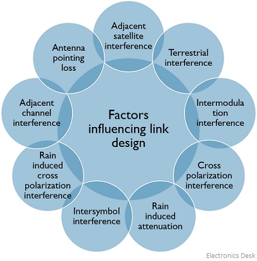
Derivation of Link Design Formula
Let Pt denotes the transmitted power. The power density is defined as the amount of power, an antenna receives in an unit area. Thus if we consider the region as spherical then the power density will be given as:![]()
And its unit is W/m2
: 4πr2 is the area of the sphere with radius r.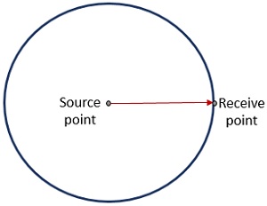
However, the above-given expression is for an isotropic type of transmitting antenna that radiates uniformly in all directions. But if the transmit antenna is directional in nature with gain Gt, then the power density will be given as:![]()
Here PtGt represents the effective isotropic radiated power along the direction of radiation of the directional antenna.
For Pt in watts, EIRP is written as:![]()
If the antenna has effective aperture Ae at the receiver end, then the total received power will be given as:![]()
Since, Ae = ηA
: Ae represents aperture efficiency,
A shows the physical area of the mouth of the antenna
However, we know![]()
: Gr is the receiver gain and λ is the wavelength
Thus, Ae can be written as,![]()
On substituting the value of Ae in the above-given equation of Pr, we will get,![]()
The above-given equation is the link equation and is used for the calculation of the power budget.
Representing the link equation in the form of decibels, we will get,![]()
On simplifying, we can have,![]()
Hence, with this equation, transmit power, transmit and receive antenna gains, receive power, distance, and wavelength of operation can be calculated.
Link Budget Calculation
In the calculation of the link budget, losses involved in transmission play a crucial role. Let us understand each transmission loss separately.
Transmission Losses
EIRP acts as the input power to the transmission line that is needed to be transmitted at the other end. However, in actuality, the total EIRP is not transmitted to the receiver end due to the losses involved in between. These losses that change the power received at the other end can be constant or variable. The constant losses are determined through statistical data while some are dependent on the weather conditions, especially rainfall.
There are various factors on which these losses depend thus the conditions are as follows:
Free-space transmission
The power received at the other end will be given as:![]()
Here GR represents the gain of the receiving antenna and r is the distance between transmitter and receiver
![]()
From the above expression, it is clear that the free space loss is a function of the square of the distance and frequency.
Feeder Losses
These are the losses at the receiver end due to the presence of couplers, filters, and waveguides thus known as receiver feeder losses, and add to free space loss. These same losses are noticed at the transmitter end also, however; these are not inclusive in the EIRP.
Antenna misalignment losses
The alignment of the earth station and satellite link antenna must provide maximum gain value. So, whenever there is some kind of mismatching in the alignment of the two then such losses are regarded as antenna misalignment losses.
The figure given below represents the alignment between the earth station and satellite for maximum gain.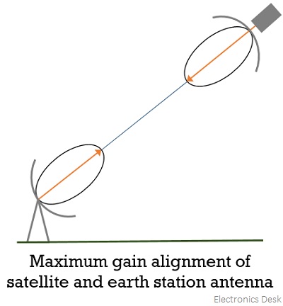
However, when there is a misalignment between the earth station and satellite then there will be an off-axis loss, and this off-axis loss at the earth station is referred to as antenna pointing loss. Its value is between 0.2 to 0.9 dB.
This is clearly shown in the figure given below: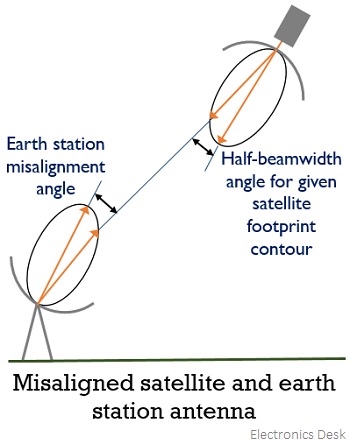
Along with pointing loss, another misalignment loss can be due to misalignment in the direction of polarization. These losses are quite small. Thus, antenna misalignment loss is inclusive of pointing loss as well as polarization loss. These losses are determined through statistical data that are taken into consideration according to the errors from various earth stations while the complete estimation is inclusive of losses associated with uplink and downlink.
Atmospheric and Ionospheric losses
The various gases present in the atmosphere lead to cause losses due to absorption of the transmitted signal and are generally some fraction of decibel. These are denoted as [AA]. Now, coming to ionospheric losses, so these are basically depolarization losses sometimes called polarization mismatch loss thus denoted as [PL].
Link-Power Budget Equation
EIRP is the input power to the transmission link. We have recently discussed the losses involved while transmitting the signal from one end to another. Thus, the power received will be given by:![]()
FSL i.e., free space loss is regarded as the major source of loss in the ground-satellite link.
We have recently discussed the various losses that correspond to free space loss. Thus the losses can be written by the equation given below:![]()
Thus, the received power decibel equation will be given as:![]()
: [PR] is the received power,
[EIRP] is the effective isotropic radiated power,
[FSL] denotes free-space spreading loss,
[RFL] denotes receiver feeder loss,
[AA] is the atmospheric absorption,
[PL] is the polarization mismatch loss and
[AML] is antenna misalignment loss.
System Noise
From the above discussion, it is clear that the power received at the other end is quite small. However, by amplifying the signal to the desired level the strength of the received signal can be raised. But you must note here that some form of noise exists at the input and the original signal must necessarily have more strength than the noise component as only then the amplification will be justified as the amplifier amplifies the signal as well as noise to the same extent.
Electrical noise in the equipment is generally, the result of random thermal motion of electrons within the active and resistive devices at the receiver. The antenna picks the thermal noise as radiation.
The expression for noise power generated by thermal noise source is given as:![]()
: TN is the equivalent noise temperature,
BN is the equivalent noise bandwidth and
k represents Boltzmann’s constant whose value is 1.38 * 10-23 J/K
Here bandwidth is in hertz and temperature is in kelvins.
In the case of thermal noise, we have a flat frequency spectrum, thus, the noise power per unit bandwidth is constant. This is known as noise power spectral density and is denoted by N0. Thus, is given by the expression:![]()
You must note here that the noise temperature from various sources can be added to have the value of overall noise.
Antenna Noise
Noise is introduced by the satellite and the antenna present at the ground station. The antenna noise is classified as:
- Sky-noise
- Noise from the antenna
Sky noise corresponds to the microwave radiations distributed over the universe and is present due to the existence of matter with a finite temperature. We know that satellites are directed towards the surface of the earth thus receives the thermal radiation coming from it. Here the equivalent noise temperature is around 290K. The antenna losses add to the noise received as radiation.
When clear sky condition is considered then the overall noise temperature in C-band is 60K while that in Ku-band is 80K.
Carrier to Noise Ratio (C/N)
It is defined as the ratio of carrier power to the noise power at the input terminals of the receiver and is a measure of the performance of the satellite link.
Thus, is expressed as:![]()
On substituting the values of PR and PN in the above equation,![]()
We know that the ratio of G and T specifies the performance of the system receiving the signal, thus the gain of the receiving antenna GR and noise temperature of the system i.e., TS can be combinedly written as:![]()
Thus, the modified equation will be:![]()
Since we know,![]()
Therefore,![]()
We can write it as:![]()
Hence![]()
Substituting the value of CN in the above equation, we will get,![]()
The above expression defines the ratio of carrier to noise power density.