Satellite Downlink or downlink of satellite circuit is a feeder link that transmits the signal from satellite down towards the ground-based station i.e., earth station. The downlink includes the factors that affect the transmission from satellite to earth station.
It can be understood more easily by considering that downlink denotes a link down from the satellite to the earth station. The process that involves downlink operation is sometimes referred to as download.
Content: Satellite Downlink
Introduction
It is known to us that satellite communication enables us to send data from one end to another by using a satellite in space. It operates in a way that signal from an earth station is transmitted towards the satellite and further the satellite retransmits the signal towards another earth station.
In our previous content on satellite uplink, we have discussed how the signal from the earth station is transmitted to the satellite. However, when the satellite transmits the achieved uplink signal back towards the ground then it is known as a downlink. The frequency of the signal during uplink and downlink is known as uplink frequency and downlink frequency respectively.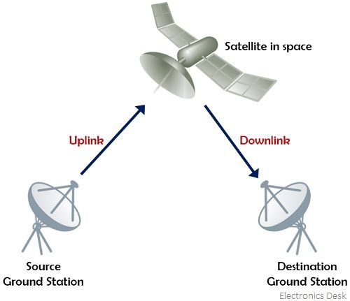
It is to be noted here that uplink and downlink frequencies must be different. This is due to the fact that if the two will be the same then the close presence of uplink and downlink antenna will lead to jamming of signals. Another important point regarding the separation of uplink and downlink frequency signal at the satellite is to use filters. Here low pass filters can be used that can block the high-frequency component of the uplink signal and can pass the low-frequency component constituting the downlink signal.
Downlink Design
Designing a downlink is not much difficult. However, exist some necessary requirements that must be fulfilled.
Requirements for Downlink Design: In the downlink configuration, the transmitting antenna for sending the downlink signal and amplifier is present at the satellite itself. Due to this, the overall size of the antenna and amplifier get limited. This ultimately limits the power at the satellite, thus, in downlink operation, a small amount of power is transmitted from the satellite towards the earth-based station. Also, during the downlink operation, the output power shows dependency on the downlink signal frequencies. And we have already discussed that the downlink frequencies must necessarily be less than the uplink frequencies.
The two major requirements of downlink frequencies are as follows:
- As satellite transmitter limits the overall power transmitted through it thus downlink frequency signals should possess less attenuation than uplink frequencies.
- A low-frequency signal propagates more than the high-frequency signal for the same amount of transmitted power.
Thus, in order to fulfill the above-discussed requirements, low-frequency signals are preferred over the high-frequency signals for the downlink operation. It is to be noted here that the EIRP of satellite or gain of the receiver does not put an impact on the downlink quality. The selection of the downlink frequency is done on the basis of maximum transmitted power and associated atmospheric losses.
How does a satellite downlink work?
As discussed above satellite downlink corresponds to the transmission of a signal from the satellite towards the earth station. Here we will understand how the operation takes place.
Have a look at the figure below, illustrating the elements that are the parts of satellite downlink: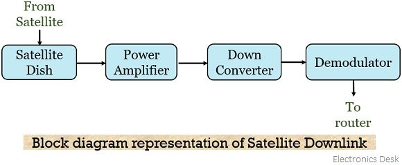
The signal from the satellite transmitter is received by the satellite dish through feed horns. The received signal is then fed to an amplifying unit i.e., a power amplifier. The input to the amplifier unit like klystron or TWTA is the upconverted signal which is amplified after the elimination of the noise component so as to get a high level of total effective power.
The amplified form of signal is now provided to the downconverter. Basically, the signal coming from the downlink is in the microwave range (1000 MHz) i.e., in the frequency band C, S, X, Ka, Ku. This when provided to the downconverter mixes the signal with an intermediate frequency in order to provide the desired downlink frequency. More specifically, we can say, the microwave frequency is converted into an L band ranging between 70 to 140 MHz. Further, this L-band signal is fed to the demodulator unit where the demodulation of the downlink signal is done and the digital data stream is extracted.
The actual data is then provided to various network components with the help of a router. Hence in this way, the signal from one earth station reaches another via satellite in satellite communication.
Equation for [C/N0]
Previously we have discussed the general equation for the carrier to noise power density (under satellite link budget) which is given as:![]()
Also, we have seen that we have added a subscript U in the above equation when uplink was considered. In a similar way, when the condition for the downlink is applied then the above equation will be modified as:![]()
: [EIRP]D is for the satellite,
[LOSSES]D denotes the earth station receiver feeder losses and
[G/T]D is for earth station receiver.
The carrier to noise power density expressed by the above equation is the one that is achieved at the detector of the earth station receiver. On assuming that the signal bandwidth B is equivalent to the noise bandwidth BN.![]()
Output back-off
Similar to the input back off which we have considered for satellite uplink a corresponding output back off must be there regarding the satellite EIRP.
It is to be noted here that there is non-linear relation between input BO and output BO. Generally, the relationship between the two is given as:![]()
Considering the satellite EIRP for saturation condition,![]()
Where,![]()
It is to be noted here that we have considered the saturation flux density at the satellite receiver in the case of the uplink. But the determination of satellite flux density at the earth station receiver is not required in the case of downlink as here the earth station is the terminal point and this received signal is not used for the purpose of saturating another power amplifier.