The earth segment in the satellite communication system consists of earth stations (earth terminals) with their respective equipment, circuits and various links to the terrestrial network. Earth stations are a major part of the earth segment and can be of fixed or mobile nature.
Earth stations are structurally quite complex as it includes the necessary units that will be able to give tracking and alignment facilities.
Content: Satellite Earth Segment
- Introduction
- Terrestrial Interface
- Transmitter and Receiver
- Antenna System
- Receive only home TV system
Introduction
As we have discussed that the earth segment includes the earth stations as its crucial part and these are none other than the transmit and receive earth stations. As far as local applications are concerned then the simplest ones are the Television receive-only system (i.e., TVRO) while for the international communication networks, the complex ones i.e., terminal stations are used. The units that provide logistic support to the satellite in space like tracking, telemetry and command functions are part of the space segment.
It is to be noted here that the stations that are present on ships at sea i.e., the mobile ones are also included in the earth segment and are useful in various commercial, aeronautical and military applications.
Let us now proceed to understand the various elements of the earth segment.
Terrestrial Interface
The earth station which is the most fundamental component of the earth segment is responsible for either receiving information from space or transmitting information towards the same. However, the transmission and reception of information must include reliability so that the actual signal quality must not get degraded. Due to this reason, its design is a crucial aspect and includes some important factors as well as the location where it is going to be present.
So, location-wise, the earth station can be present either on land, ship at sea or an onboard aircraft. While as far as factors are considered then, it includes the type of service offered, the characteristics of antenna in use, transmitter and receiver functions and the frequency band utilized.
Transmitter and Receiver
The four major subsystems of the earth station are:
- Transmitter
- Receiver
- Antenna unit
- Tracking equipment
Other than these, power supply and terrestrial interface equipment are also important.
Have a look at the block diagram representation of the transmit-receive earth station shown below:
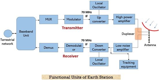
The terrestrial networks send the digital message signal to the earth station where the various units within it perform functions like filtering, multiplexing, formatting, etc. The mux combines the signals and encoding is also performed to execute error correction coding. Here extra bits are added to the actual digital information. The signal is then fed to the modulator where it gets modulated with a proper carrier signal and then up-conversion of the signal is performed up to a specified frequency level.
This signal is further provided to a high pass filter where the desired amplification is performed after which by the use of the feed system the signal is transmitted.
In the receiving scenario, the antenna at the receiving end gets the signal sent by a satellite whose amplification via low noise amplifier is done. This signal is further down-converted to the IF range and then after demodulation, lastly demuxing to separate the various signals is done. Through decoding the actual information-bearing digits is recovered and then it is provided to the terrestrial network.
The use of tracking equipment enables to keep the positional track of the satellite in space. Thus, this single unit performs 4 basic functions such as satellite acquisition, automatic, manual and program tracking.
Antenna System
This consists of units: feed system, reflector type antenna, mount along with tracking system. Let us discuss each separately,
Feed system
The combination of feed and the reflector acts as the radiating or receiving unit for the electromagnetic waves coming from or reaching towards the satellite. This comes under feed configuration and can be of three types namely,
- Axi-symmetric configuration
- Asymmetric configuration
- Axi-asymmetric configuration
Antenna Reflector
When we talk about the antenna reflector then in most of the cases, parabolic reflector acts as the main antenna element as these offer high gain. Also, these are designed to provide a better ability to focus parallel beam than other reflector types. According to the type of service which is to be offered, the following parameters are to be considered in reference to the parabolic reflector:
- Mount type
- Coverage requirement
- Size of reflector
- RMS error of reflector
- Pointing and tracking accuracy
The reflector size is concerned with the gain requirement during transmission and reception as well as the beamwidth of the antenna. Gain and beamwidth vary in direct and inverse proportionality with the antenna diameter respectively.
Receive only home TV system
The signals broadcasted directly to home TV receivers occurs in the Ku band (12 GHz), this is called direct broadcast satellite service (DBS). However, the allotted frequency band varies according to the geographic region of operation. For the large satellite dishes that receive signal the operation occurs at the C band (4 GHz). These are not simply useful in home signal reception but to form network relay relative to commercial TV outlets.
The receive-only system for Ku-band and C-band operation is different from one another mainly in terms of the operating frequency of the outdoor unit as for DBS operation they must have very high EIRP. The figure below represents the block diagram where the home terminal is used for DBS reception: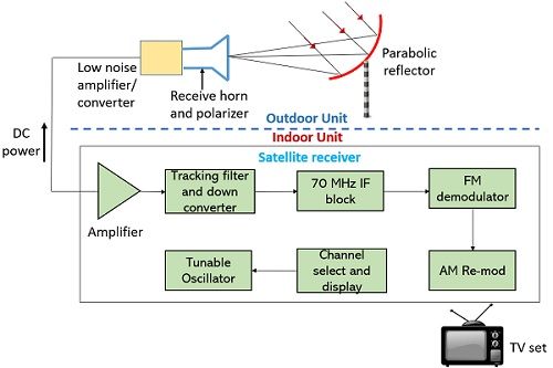
The use of the C band allows a large number of satellites availability for reception than the K-band DBS system. It offers free analog signals, free DigiCipher 2 services.
The outdoor unit of this system has a receiving antenna that directly feeds the signal to a low noise amplifier along with a converter. This combinational unit is known as LNB, a low noise block. Here the receiving antenna uses a combination of the parabolic reflector which is mounted along with a horn at the focus. The gain for the 12 GHz broadband signal is provided by the LNB where the signal gets converted into a low-frequency one. This facilitates the use of low-cost coaxial cable as a feeder to the indoor unit.
Generally, the down-converted range is between 950 MHz to 1450 MHz. Here via low noise amplification, desired SNR is achieved.