Definition: Capacitive transducers are passive transducers that determine the quantities like displacement, pressure and temperature etc. by measuring the variation in the capacitance of a capacitor.
As we know that a transducer changes a form of energy into another form. So, in the capacitive transducer, the change in the capacitance is used to measure the physical quantities.
Content: Capacitive Transducer
Principle of Capacitive Transducer
The operating principle of a capacitive transducer is variable capacitance.
Now, the question arises that how the change in the capacitance of the capacitor occurs?
Assume a parallel plate capacitor, whose capacitance is given by:
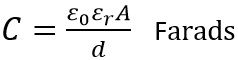
: A denots the area of the plates,
ε0 is the permittivity of free space,
εr is the relative permittivity and
d is the distance between the two plates in metre.
From the above equation is it clear that the capacitance of the capacitor is dependent on the area of the two plates, the distance between two plates and the permittivity of the material.
Hence, by varying either area, distance or permittivity, the non-electrical quantities can be determined.
So basically, it can be concluded that there exist 3 methods by which the capacitance of the capacitive transducer can be varied. The methods are:
- By the change in the area of overlapping of the two plates i.e., A
- By the change in the distance, d between the two plates
- By the change in relative permittivity of dielectric material present between the two plates.
So, let us now move further and understand, how the unknown physical quantity is being measured by causing variation in the different parameters.
Working of Capacitive Transducer
Let us discuss all the above 3 introduced methods in detail.
- By changing the overlapping area of the two capacitive plates:
The figure below shows the parallel plate capacitor, whose 2 plates have width b and are overlapped up to a length l as shown below:
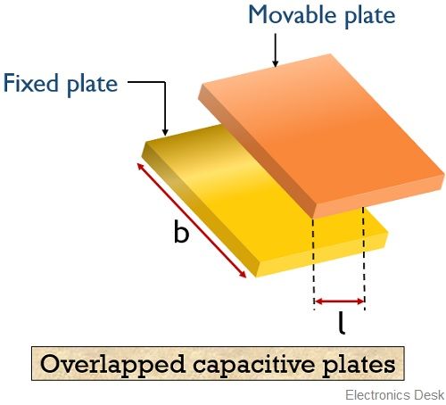
It operates in such a way that capacitance of the capacitor is proportional to the area of overlapping of the two plates.
This overlapping length is changed according to the displacement that is to be measured. Hence displacement variation allows the change in the capacitance.
We know the capacitance for a parallel plate capacitor is given as
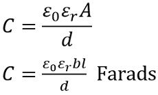
: l denotes the overlapping length and b denotes the width of the plates
The sensitivity is given as

So we can have
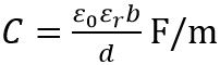
Hence by observing the above equation we can say that the sensitivity is constant. Thus, a linear curve is plotted between the capacitance and displacement except for the beginning part.
The curve between capacitance and displacement is shown below:
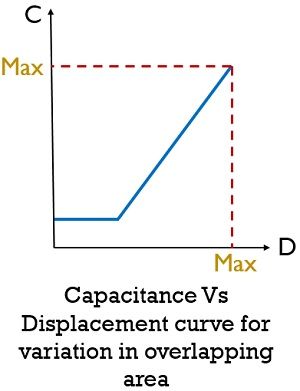
So, by varying the area of overlapping of the two plates, linear displacement can be measured accurately between the range 5 mm to 10 mm.
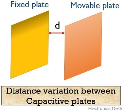
- By changing the distance between the capacitive two plates:
The operation of these capacitors is such that the capacitance of the capacitor is inversely proportional to the distance i.e., d between the plates. Hence used to determine the linear displacement.
In such transducers, among the two capacitive plates, one is stationary (fixed) while the other is mobile (movable). So, with the motion of the movable plate, the capacitance increases or decreases depending on the displacement which is to be measured.
An ac circuit is used to determine the variation in the capacitance, thereby determining the displacement of the plate.
The figure below represents the non-linear curve between displacement and capacitance:
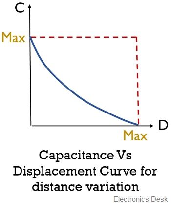
It is clearly shown here that the curve is non-linear. Hence by observing the above curve, we can say that the capacitor is highly sensitive initially. Thus we can say that these transducers are used for determining very small displacement.
Thus the sensitivity of the capacitor for change in distance is given as
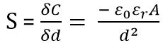
Hence we can say that the sensitivity of the transducer varies over a certain range.
- By changing the permittivity of the dielectric material:
This type of transducer operates by the variation in the relative permittivity of the dielectric material placed between the plates.
The motion of dielectric material between the plates determines the capacitance in order to determine the displacement.
The figure below represents a capacitive transducer with the variation of relative permittivity:
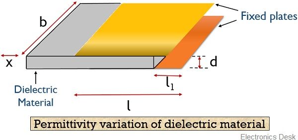
Here, the distance between the plates is d while b is the width of each plate. x denotes the displacement of dielectric material; l denotes the overlapped region of the two plates.
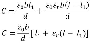
The equation for the capacitance of the transducer is given as
With the movement of dielectric material over a distance x, then capacitance shows change from C to C – ∆C
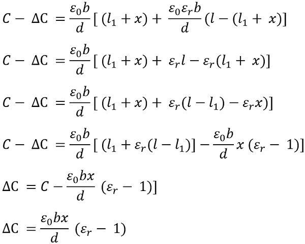
Thus we can say that the variation in capacitance shows proportionality with the displacement that is to be measured. Generally using this method displacement ranging from 1 μm to 10 mm can be measured.
Advantages of Capacitive Transducer
- These transducers exhibit least loading effects as it offers extremely high input impedance.
- The frequency response of these transducers is excellent.
- Highly sensitive.
- Low power consuming transducers.
- It provides high resolution.
Disadvantages of Capacitive Transducer
- Due to high output impedance, a complicated measuring circuit at the output is needed.
- To reduce the chances of the pickup, electrostatic screening must be given to these transducers.
- The change in external factors like temperature, humidity etc. hinders the capacitance of the transducers.
Applications of Capacitive Transducer
- As these transducers are able to measure both linear and angular displacements with great sensitivity. Hence used to determine distances up to around 30 m.
- Not only the displacement but also force and pressure can be detected. These first changes the force into displacement and with the change in displacement, the capacitance is allowed to vary.
- Also, humidity can be measured by a capacitive transducer. As with the variation in humidity, the permittivity also varies and this resultantly changes the capacitance of the capacitor.
- With the help of mechanical modifiers density, volume, weight etc. can also be measured.
So, from this discussion, we can conclude that capacitive transducers utilize the property of variable capacitance in order to determine the quantities like displacement, pressure, temperature etc.