Definition: Directional Coupler is a passive network that is used to measure the microwave power delivered to the load. It is a waveguide with 4-ports which aims at sampling of microwave power.
In a nutshell, directional couplers allow the determination of delivered power to the load from the power actually being transmitted by the source.
The figure below represents the structure of a directional coupler:
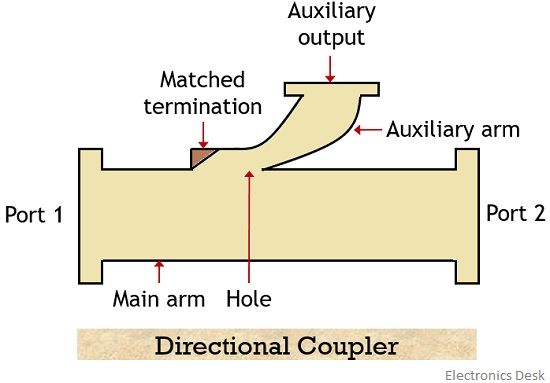
Whenever any transmitting unit transmits a certain amount of power, then for proper application it becomes necessary to have the idea about whether the complete power is received or it is some value lower or higher than the originally transmitted power.
So, for this purpose directional couplers are used.
Two-hole Directional Coupler
A two-hole directional coupler is a device in which two connected waveguides have 2 holes present between them. One waveguide is known as primary main waveguide while the other is said to be the auxiliary waveguide.
The figure below represents a two-hole directional coupler having 4 ports:
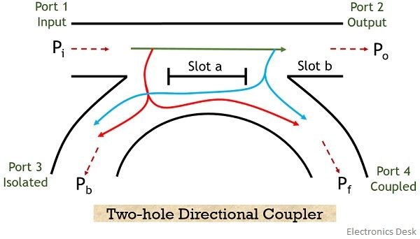
Suppose a microwave signal is to be transmitted from port 1 to 2. As we can see that 2 slots namely ‘a’ and ‘b’ are present over here.
So when the signal is transmitted inside the main waveguide then on passing through slot ‘a’ and part of energy gets radiated towards the auxiliary waveguide. While the rest proceeds towards slot ‘b’.
Further, some part of the wave proceeding towards the output gets radiated towards the auxiliary waveguide again through the second hole.
Both the time the wave reaching the auxiliary waveguide travels in the forward direction (i.e., towards port 4) and backward direction (i.e., towards port 3) as shown in the above figure.
The wave that travels in auxiliary waveguide towards port 4 will be in phase with the signal in the main waveguide and causes reinforcement of the signal. While the wave travelling towards port 3 will be 180⁰ out of phase with the originally transmitted signal.
Therefore, the signal at port 3 due to both the slots cancels each other. Thus the port 3 is generally known as isolated port. Port 1 is the input and port 2 is the output port respectively. While port 4 is considered as a coupled port.
Thus the power at 4 different ports can be specified as
Pi = input power
Po = output power
Pb = backward power
Pf = forward coupled power
An ideal condition of directional coupler requires the backward power Pb to be 0. Thus the input power gets divided in an equal manner between port 2 and 4.
Parameters of Directional Coupler
The 4 fundamental parameters that measure the performance of any directional coupler are as follows:
- Coupling factor: It decides the level of coupled power from the originally incident power inside the waveguide.
Thus is given in the form of the ratio of input power to the forward coupled power.
So, the coupling factor denoted as C is given as: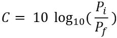
- Directivity: Directivity of the coupler is determined on the basis of forward and backward power in auxiliary waveguide.
More simply, it is the ratio of forward coupled power to the backward power. Thus is given as: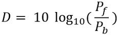
- Isolation: Isolation is the parameter that defines the directional nature of the coupler. It is defined as the ratio of input power at the main waveguide to the backward power at the auxiliary waveguide.
Thus is given as: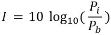
- Return loss: For signal transmission, return loss defines the actually transmitted power to the received power at the main guide.
It is denoted by R and is given as: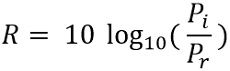
The noteworthy point over here is that all the parameters of the directional couplers are measured in dB.
Scattering Matrix of Directional Coupler
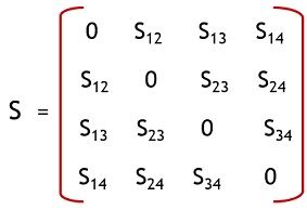
As directional couplers are 4-port devices. Thus generally it is given as:
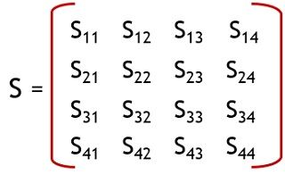
All the four ports of the directional coupler are matched perfectly. Thereby ensuring that no power gets reflected back towards the port.
Thus the diagonal elements will be 0.
S11 = S22 = S33 = S44 = 0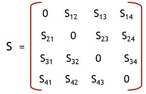
By property of symmetricity,
Since Sij = Sji
Therefore
S12 = S21 ; S13 = S31 ; S14 = S41
S23 = S32 ; S24 = S42 ; S34 = S43
So, the matrix will be given as:
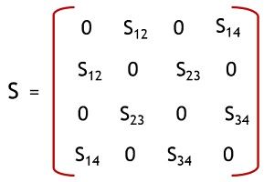
Ideally port 1, 3 and port 2, 4 are isolated wrt each other. So,
S13 = S31 = 0
S24 = S42 = 0
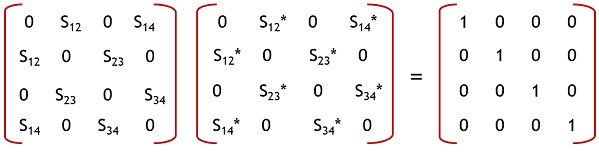
According to the identity property
[S] [S*] = I
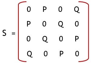
Further,
Forward power
S12 = S34 = P
While the coupled power
S14 = S23 = Q
Thus the scattering matrix of the directional coupler will be given as:
Applications
It is used to measure incident and reflected power along with measuring voltage standing wave ratio values. It also provides the path to the signal towards the receiver and used for the purpose of unidirectional wave launching.