Definition: Encoders (or binary encoders) are the combinational circuits that are used to change the applied input signal into a coded format at the output. These digital circuits come under the category of medium scale integrated circuit.
Basically, these are used to minimize the number of data lines as well as to code the input data.
In binary encoders among all the input lines, only a single input line gets activated at a time. And the logic circuitry present inside the encoder converts this active signal into coded binary format.
Suppose for an encoder the number of input lines is 2n then the output lines will be n.
Thus less number of data lines are required by encoded data to get transmitted from an end to another.
4:2 Binary Encoder
As we have recently discussed the relation between input and output data lines. So, let us understand how a 4:2 binary encoder operates.
The figure below represents 4:2 binary encoder:
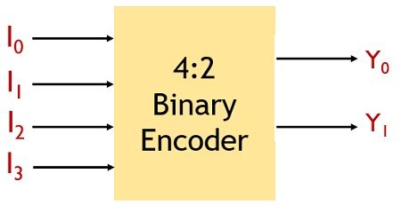
Here 4 input lines are present and for 4 input lines, by the relation 2n, the number of output must be 2. Hence it is said to be 4:2 encoder, because of having 4 input lines and 2 output lines.
Let us see the operation of 4:2 binary encoder in detail.
We know in case 4 of input lines the applied input bits will be 00, 01, 10, 11 denoting the input lines I0, I1, I2, I3. As we have already mentioned that at a time only a single input gets activated. So, that activated input will be generated at the output of the encoder.
The figure shown below will provide you with a better idea about the operation performed by 4:2 encoder:
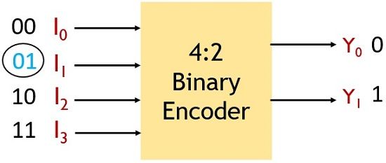
Suppose here I1 input line is activated then, at the output Y0 line will hold 0 and Y1 will hold 1. As I1 denotes 01 binary value.
The truth table of 4:2 binary encoder is given below:
| I0 | I1 | I2 | I3 | Y0 | Y1 |
|---|---|---|---|---|---|
| 0 | 0 | 0 | 1 | 0 | 0 |
| 0 | 0 | 1 | 0 | 0 | 1 |
| 0 | 1 | 0 | 0 | 1 | 0 |
| 1 | 0 | 0 | 0 | 1 | 1 |
Also, the logic circuit involved in 4:2 binary encoder is shown below:
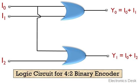
This circuit represents the logic circuitry behind the operation performed by 4:2 binary encoder.
Types of Encoders
Encoders are classified into 4 categories:
- Decimal to BCD Encoder
- Octal to Binary Encoder
- Hexadecimal to Binary Encoder
- Priority Encoder
Among all the above-given encoders. The priority encoders were developed to overcome the disadvantages associated with other 3 encoders. Here, we will see why priority encoders show an advantage over normal binary encoders.
Decimal to BCD Encoder
A decimal to BCD encoder has 10 input lines while 4 output lines. The 10 input lines correspond to decimal values and 4 output lines correspond to BCD code.
The figure below represents the decimal to BCD encoder:
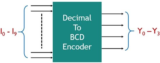
Here, the 10 input lines from I0 to I9 shows the decimal input and Y0 to Y3 shows the BCD output.
The figure below shows the truth table for decimal to BCD encode
| Input / Output | Y0 | Y1 | Y2 | Y3 |
|---|---|---|---|---|
| I0 | 0 | 0 | 0 | 0 |
| I1 | 0 | 0 | 0 | 1 |
| I2 | 0 | 0 | 1 | 0 |
| I3 | 0 | 0 | 1 | 1 |
| I4 | 0 | 1 | 0 | 0 |
| I5 | 0 | 1 | 0 | 1 |
| I6 | 0 | 1 | 1 | 0 |
| I7 | 0 | 1 | 1 | 1 |
| I8 | 1 | 0 | 0 | 0 |
| I9 | 1 | 0 | 0 | 1 |
So, from the above table we can conclude that
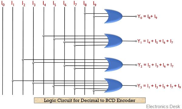
Y0 = I8 + I9
Y1 = I4 + I5 + I6 + I7
Y2 = I2 + I3 + I6 +I7
Y3 = I1 + I3 + I5 + I7 + I9
The figure below shows the logic circuit for decimal to BCD encoder:
Octal to Binary Encoder
In octal to binary encoder 8 input and 3 output lines are present.
The applied input to the encoder corresponds to the octal values while the output shows the binary values.
The figure below represents octal to binary encoder:
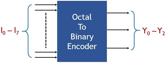
Here, I0 to I7 represents the octal input and Y0 to Y2 shows the binary output values.
So, let us have a look at the truth table of octal to binary encoder:
| Input / Output | Y0 | Y1 | Y2 |
|---|---|---|---|
| I0 | 0 | 0 | 0 |
| I1 | 0 | 0 | 1 |
| I2 | 0 | 1 | 0 |
| I3 | 0 | 1 | 1 |
| I4 | 1 | 0 | 0 |
| I5 | 1 | 0 | 1 |
| I6 | 1 | 1 | 0 |
| I7 | 1 | 1 | 1 |
From the truth table, we can conclude that
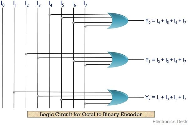
Y0 = I4 + I5 + I6 + I7
Y1 = I2 + I3 + I6 + I7
Y2 = I1 + I3 + I5 + I7
Hence the logic circuit will be given as:
Hexadecimal to Binary Encoder
The hexadecimal to binary encoder contains 16 input lines as well as 4 output lines. So, the input provided shows the hexadecimal count and the output represents the binary values.
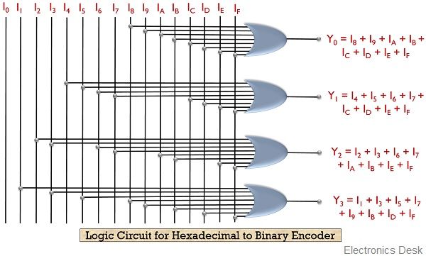
The figure shown below represents the hexadecimal to binary encoder:
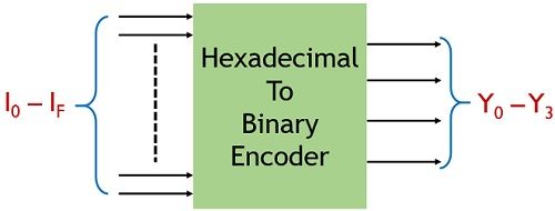
Here, I0 to IF represents the hexadecimal input and Y0 to Y3 represents binary output.
Let us have a look at the truth table of hexadecimal to binary encoder:
| Input / Output | Y0 | Y1 | Y2 | Y3 |
|---|---|---|---|---|
| I0 | 0 | 0 | 0 | 0 |
| I1 | 0 | 0 | 0 | 1 |
| I2 | 0 | 0 | 1 | 0 |
| I3 | 0 | 0 | 1 | 1 |
| I4 | 0 | 1 | 0 | 0 |
| I5 | 0 | 1 | 0 | 1 |
| I6 | 0 | 1 | 1 | 0 |
| I7 | 0 | 1 | 1 | 1 |
| I8 | 1 | 0 | 0 | 0 |
| I9 | 1 | 0 | 0 | 1 |
| IA | 1 | 0 | 1 | 0 |
| IB | 1 | 0 | 1 | 1 |
| IC | 1 | 1 | 0 | 0 |
| ID | 1 | 1 | 0 | 1 |
| IE | 1 | 1 | 1 | 0 |
| IF | 1 | 1 | 1 | 1 |
Thus we can conclude from the above table:
Y0 = I8 + I9 + IA + IB + IC + ID + IE + IF
Y1 = I4 + I5 + I6 + I7 + IC + ID + IE + IF
Y2 = I2 + I3 + I6 + I7 + IA + IB + IE + IF
Y3 = I1 + I3 + I5 + I7 + I9 + IB + ID + IF
So, the logic circuit will be given as
Priority Encoder
Priority encoders are a special type of encoders that were developed to eliminate the drawback associated with normal encoders.
As when multiple inputs are high then the encoder will not be able to correctly respond to any one of the input. As in this case, an ambiguity will get generated.
Due to this, priority encoders were taken into consideration.
In priority encoders, with movement in downward direction, priority increases.
This means that the LSB will contain the lowest priority while the MSB has the highest priority.
Consider the 4:2 priority encoder shown below:
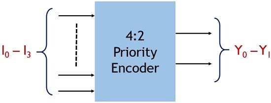
Here I0 to I3 represents the 4 input lines and Y0 and Y1 shows the output lines. Also, the priority encoder contains a 3rd output line V which is termed as a valid bit.
This bit checks the availability of low signal at all the inputs. If all the 4 inputs are low, then at the output the valid bit will show 0 at the output.
So, we can say that at any point of time, if I3 will be high, then the circuit does not need to check any other input line. As among all the input data lines shown above, I3 holds the highest priority.
Thereby automatically the output will be generated according to the input I3. So, in this way, the ambiguity of the generated result can be overcome by the priority encoders.
The truth table of 4:2 priority encoder is given below:
| I0 | I1 | I2 | I3 | Y0 | Y1 | V |
|---|---|---|---|---|---|---|
| 0 | 0 | 0 | 0 | * | * | 0 |
| 1 | 0 | 0 | 0 | 0 | 0 | 1 |
| * | 1 | 0 | 0 | 0 | 1 | 1 |
| * | * | 1 | 0 | 1 | 0 | 1 |
| * | * | * | 1 | 1 | 1 | 1 |
From the above-given truth table, we can conclude that
When both the applied input is low then this shows the absence of valid input so, in this case, the output will be don’t care condition hence valid bit will set to 0.
Further when we see that input I0 is high then it is needed to check the state of I1, I2 and I3. As in this case, all the rest 3 inputs must be low. So, the output will be generated according to the input line I0.
Proceeding further, when input I1 will be high then there exists no need to check the state of I0 as it holds the least priority. But, still the input lines I2 and I3 both has to be low. So output generated will be according to I1.
In the same way, in the case of I2 only state of I3 is required to be checked. As it must be low to get the output according to I2.
But when I3 goes high then rest 3 inputs falls in don’t care condition. As I3 has the highest priority and the output generated accordingly.
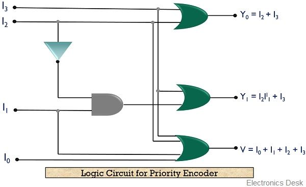
So, it can be concluded that
Y0 = I2 + I3
Y1 = I2 II1 + I3
V = I0 + I1 + I2 + I3
The logic circuit is given as
So, this is all about binary encoders and its types.